
Page 54 - ARNM-3-2
P. 54
Advances in Radiotherapy
& Nuclear Medicine Shielding exaggeration in medical linac bunkers
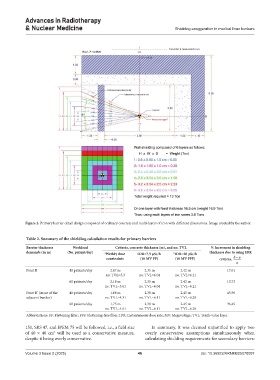
Figure 2. Primary barrier detail design composed of ordinary concrete and multi-layers of iron with different dimensions. Image created by the author.
Table 2. Summary of the shielding calculation results for primary barriers
Barrier thickness Workload Criteria, concrete thickness (m), and no. TVL % Increment in shielding
demands (in m) (No. patient/day) a Weekly dose IDR=7.5 µSv/h b IDR=20 µSv/h thickness due to using IDR
constraints (10 MV FF) (10 MV FFF) criteria, ba−
a
Point B 40 patients/day 2.07 m 2.35 m 2.42 m 17.01
no. TVL=5.3 no. TVL=6.04 no. TVL=6.21
60 patients/day 2.18 m 2.35 m 2.42 m 10.73
no. TVL=5.61 no. TVL=6.04 no. TVL=6.21
Point B’ (maze of the 40 patients/day 1.68 m 2.38 m 2.45 m 45.96
adjacent bunker) no. TVL=4.31 no. TVL=6.11 no. TVL=6.29
60 patients/day 1.75 m 2.38 m 2.45 m 36.45
no. TVL=4.61 no. TVL=6.11 no. TVL=6.29
Abbreviations: FF: Flattening filter; FFF: Flattening-free filter; IDR: Instantaneous dose rate; MV: Megavoltage; TVL: Tenth-value layer.
151, SRS 47, and IPEM 75 will be followed, i.e., a field size In summary, it was deemed unjustified to apply two
of 40 × 40 cm will be used as a conservative measure, overly conservative assumptions simultaneously when
2
despite it being overly conservative. calculating shielding requirements for secondary barriers:
Volume 3 Issue 2 (2025) 46 doi: 10.36922/ARNM025070007