
Page 119 - DP-2-1
P. 119
Design+ Feasibility of shell fusion technology in jewelry design
Table 1. Production rate of different processes for different materials
Material Production rate (unit[s]/h)
Manual CAD/CAM casting Lost wax SLA casting SLA slurry SLM SFT
Ceramic <0.5 - 1 - <0.1 - 1 – 10
High-noble metal alloy <0.5 1 – 2 1 – 50 0.5 – 10 - - 1 – 10
Noble metal alloy <0.5 1 – 2 1 – 50 0.5 – 10 - - 1 – 10
Predominately base-metal <0.5 1 – 2 1 – 50 0.5 – 10 - 1 1 – 10
Note: Data were obtained from references. 6-9
Abbreviations: CAD: Computer-aided design; CAM: Computer-aided manufacturing; SLA: Stereolithography; SLM: Selective laser metal; SFT: Shell
fusion technology.
material. Therefore, it is possible to identify either the low A B
productivity or lack of capability of the manufacturing
processes with regard to jewelry making.
2. Material and methods
Using the appropriate software, jewelry designs are first
created, sketched, and then converted to CAD format.
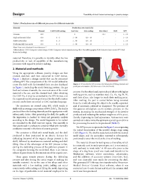
Figure 1 displays a design model that can be processed
utilizing SFT. The components of the 3D model utilized to
create the shell with the intended form are also displayed Figure 1. 3D models for SFT process. (A) Schematic of filling channel and
in Figure 1, including the mold-forming portion, the gas jewel part orientation. (B) Schematic of the shell mold.
feed and release channels, the reservoir area of the metal process. On the other hand, materials and alloys with higher
material to be cast, and the channel feed. After obtaining melting points, such as stainless steel, Cu, Au, Ag, Pt, Ni,
the CAD file, it may be converted to the STL format, and and their alloys, take longer to reach their melting point.
the required modifications performed for the shell creation After melting, the part is cooled before being removed
process can be later converted to CNC machine language.
from the mold, allowing the object to be readily separated
The specimens are created using SFT, which results in and, if necessary, polished or sharpened. The presence of
shells with an average composition of 80% ZrSiO . The shell is this gaseous atmosphere exerts isostatic pressure on the
4
produced from the feeding channels, and the appropriate mold system, increasing the mechanical strength of the jewelry
subsequently forms. After generating the shell, the quality of produced and reducing the surface roughness of the piece,
the impression is checked by visual and geometric analysis thereby improving its final appearance. Various tests were
according to the design. The metal fragments to be melted carried out to determine the optimum operating conditions
are deposited in the shell reservoir region. This assembly is for processing the mold to be produced (Table 2).
then positioned in a refractory container filled with thermally The SFT process is represented in Figure 2, encompassing
conductive material in the form of ceramic powder.
the initial visualization of the jewelry design stage using
The container is filled with metal beads, and the shell CAD (Figure 1). The shell is manufactured with the desired
produced is then positioned in an electric furnace for mold shape, and the particulate material is subsequently
debinding (removal of the organic charge present in the positioned to enter the mold at the time of melting.
shell), followed by simultaneous material melting and shell The material chosen for testing was a silver alloy, which
filling. One of the advantages of the SFT process is that, is commonly used to make prototypes, as it is economical,
during the debinding process of the polymers present in soft, and easy to work with. A 3D scan of a piece in the
9
the composite forming the mold/shell, there is an intense shape of a dog bone jewel was made and transferred to
release of gases from the decomposition of the organic part. Meshmixer software, where corrections, adjustments,
These gases remain present during the debinding and the addition of accessory systems (reservoirs, feed,
process and also during the initial stages of melting the and vent channels) were made for processing the shell.
metallic material. As in the case of tin alloys and other The generated STL file was then transferred to Zirconium
materials with a low melting point, pulling can occur Medical Devices’ Ceramic Slicer software, where it was
concurrently with melting and filling the mold, depending converted into G-code format and sliced; the ceramic shell
on the type of particulate metal material employed in the mold was then produced.
Volume 2 Issue 1 (2025) 3 doi: 10.36922/dp.3869