
Page 109 - IJB-7-3
P. 109
Chen, et al.
A
B
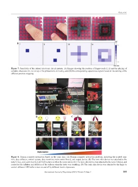
Figure 7. Sensitivity of the printed electronic circuit pattern. (A) Images showing the position of finger-touch (i, ii) and the placing of
complex structures (iii, iv) on top of the printed ionic skin array, and (B) the corresponding capacitance signals based on the sensing of the
different pressure mapping.
A
B C
D
Figure 8. Human-computer interaction based on the ionic skin. (A) Human-computer interaction platform, including the printed ionic
skin, data collector, control system, data transition, main control board, and output device. (B) The ionic skin device was attached to the
tester’s face, and controlled the LED bulb to turn on when the tester smiled (C) The ionic skin device was attached to the tester’s throat, and
controlled the inflation and deflation of the balloon when the tester was breathing. (D) The ionic skin device was attached to the finger to
control different LED bulbs to turn on and off by different levels of pressure.
International Journal of Bioprinting (2021)–Volume 7, Issue 3 105