
Page 184 - IJB-9-4
P. 184
International Journal of Bioprinting 3D-printed middle ear prostheses
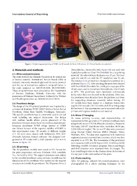
Figure 1. 3D planning and printing of PORP. (A) 3D model. (B) Form 3 3D printer. (C) Printed batches on a platform.
2. Materials and methods (Formlabs Inc., Somerville, MA; Figure 1B) was used with
liquid photopolymer Clear V4 (Formlabs Inc.) as printing
2.1. Ethics and permissions material. The selected layer thickness was 25 µm. The laser
The study fulfilled the Helsinki Declaration for ethical use spot size was 85 µm and the XY resolution was 25 µm.
of human material. Institutional Review Board (IRB) at The batches to be printed were designed and printed on a
Helsinki University Hospital approved the study protocol platform (Figure 1C). After printing, the parts were cleaned
and the use of anonymous cadaveric temporal bones in with FormWash (Formlabs Inc.) with pure isopropanol for
the study (approval no. §49/29.10.2020, HUS/58/2020). 10 min and cured in FormCure (Formlabs Inc.) for 15 min
These temporal bones were dissected at the Department at 60°C. The prostheses were numbered continuously
of Forensic Medicine, Helsinki University with the in the order they were located on the platform. After that,
permission of National Supervisory Authority for Welfare the prostheses were detached from the platform and from
and Health (permission no. 6834/06.01.03.01/2013). the supporting structures manually before testing. All
2.2. Prosthesis design 3D models have been shared in a database (https://doi.
The design of the 3D-printed prosthesis was inspired by a org/10.5281/zenodo.7281752) with a full 3D printing setup
commercial titanium PORP (MNP Malleus Notch Partial file for Form 3. The experiments can be repeated with other
Prosthesis, Heinz Kurz GmbH, Dusslingen, Germany). printers with a given resolution and material.
This specific prosthesis type is commonly used in clinical 2.4. Micro-CT imaging
work including our surgical department. The design To assess printing accuracy and reproducibility, 14
with malleus handle allows precise placement of the representative first-generation 3D-printed prostheses were
prosthesis between stapes head and malleus manubrium/ imaged with micro-CT (GE, Phoenix v|tome|x s, Wunstorf,
tympanic membrane. PORP design instead of TORP Germany; 240 kV microfocus tube, resolution 40.09 μm,
was chosen because of the superior stability of PORP in 2,500 different angles). The micro-CT data were processed
this experimental setup. 3D models of different lengths using Thermo Fisher PerGeos 2020.2 (Thermo Fisher,
(1.5–3.0 mm) were created with Solidworks 2019–2021 Waltham, MA). The data were segmented with watershed
(Dassault Systèmes, France) software. The designed first- segmentation and converted into a surface, which was then
generation 3D model with a shaft diameter of 0.4 mm is exported to an STL file. The dimensions of the prostheses
shown in Figure 1A. were measured with a GOM Inspect 2021 (Carl Zeiss GOM
2.3. 3D printing Metrology GmbH, Germany) program. Functional length
The 3D prosthesis models were saved in STL format for and shaft diameter were measured from the images. The
the print preparation software (Preform 3.9.0; Formlabs functional length refers to the distance from the bottom of
Inc., Somerville, MA). The support structures were added the cup part to the outer surface of the plate.
to the modeled prostheses using software. In addition, the 2.5. Photo stacking
dimensions of the prosthesis were marked on the support After 3D printing, selected 3D-printed prostheses were
structures to identify the prostheses. The 3D printer Form 3 photographed by a photo stacking technique. In the
Volume 9 Issue 4 (2023) 176 https://doi.org/10.18063/ijb.727