
Page 221 - v11i4
P. 221
International Journal of Bioprinting Vector-based G-code generation for biofabrication
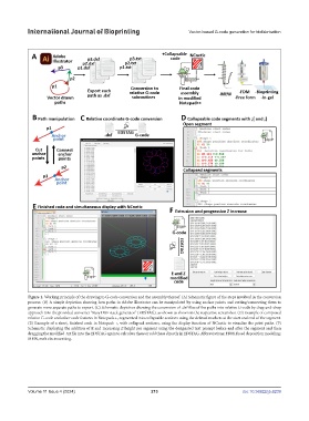
Figure 1. Working principle of the drawing to G-code conversion and the assembly thereof. (A) Schematic figure of the steps involved in the conversion
process. (B) A simple depiction showing how paths in Adobe Illustrator can be manipulated by using anchor points and cutting/connecting them to
generate more separate paths to export. (C) Schematic depiction showing the conversion of .dxf files of the paths into relative G-code by drag-and-drop
approach into the provided converter “Easy DXF stack generator” (EDSTAG), as shown as shown in the respective screenshot. (D) Example of composed
relative G-code and other code features in Notepad++, segmented into collapsable sections using the defined markers at the start and end of the segment.
(E) Example of a short, finished code in Notepad++, with collapsed sections, using the display function of NCnetic to visualize the print paths. (F)
Schematic displaying the addition of E and increasing Z height per segment using the designated text prompt before and after the segment and then
dragging the modified .txt file into the EDSTAG again to calculate these or add these directly in EDSTAG. Abbreviations: FDM, fused deposition modeling;
MEW, melt electrowriting.
Volume 11 Issue 4 (2024) 213 doi: 10.36922/ijb.6239