
Page 223 - v11i4
P. 223
International Journal of Bioprinting Vector-based G-code generation for biofabrication
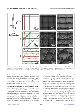
Figure 2. Basic grid-shaped melt-electrowritten scaffolds. Illustrations of the scaffold lattices in the vector drawing program on the left and their printed
equivalents from a top and side view in the middle and right, respectively. (A) An example of a simple box-shaped scaffold. (B) A box-shaped scaffold with
fibers crossing over in the middle of the box in the lower layers. (C) A hexagon-like scaffold with an intersecting hanging fiber layer.
built-in functions, such as Image Trace, which can convert may not be compatible with the specific requirements of
23
images into vector graphics. These vector images consist the application. If the code is generated by the slicer, the
of paths that can be combined or simplified, enabling sequence in which the rings are printed is determined by
quicker generation of the desired print shape. This was the program’s algorithm, which may not be compatible
demonstrated with the conversion and printing of the with our application, as exemplarily shown in Figure S3A,
institute’s logo in Figure 3G and H. Supporting Information. Moreover, the printhead may
travel over areas that should not be exposed to heat, as
3.3. Applications of FDM 3D printing in laboratory the slicer cannot anticipate where subsequent prints will
Fused deposition modeling (FDM) 3D printing is a widely be, and there is no better pathfinding option available.
used technique that relies on CNC-based programming. Using the drawing-to-G-code method, these problems
Although FDM slicing programs can print most objects, can be resolved by manually drawing the rings and the
they have limitations in terms of adaptability. In certain paths in between them, thus defining the proper printing
scientific or production applications, the slicing algorithm sequence, as demonstrated in Figure 4A. This method also
may not produce an ideal path or printing sequence. For facilitates the combination of multiple technologies. For
example, when reinforcing electrospun or MEW substrates example, if the substrate is laser-cut before FDM printing,
with FDM, the slicer generates a sequence of prints that the reinforcements can follow the same geometry, and the
Volume 11 Issue 4 (2024) 215 doi: 10.36922/ijb.6239