
Page 13 - MSAM-4-3
P. 13
Materials Science in Additive Manufacturing Ceramic vat photopolymerization
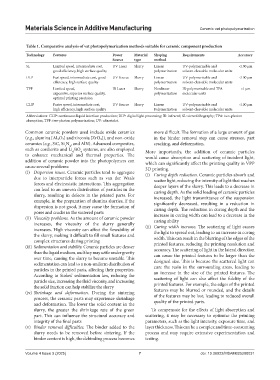
Table 1. Comparative analysis of vat photopolymerization methods suitable for ceramic component production
Technology Features Power Material Shaping Requirements Accuracy
Source type method
SL Limited speed, intermediate cost, UV Laser Slurry Linear UV-polymerizable and <100 μm
good efficiency, high surface quality polymerization solvent-cleavable molecular units
DLP Fast speed, intermediate cost, good UV Source Slurry Linear UV-polymerizable and <100 μm
efficiency, high surface quality polymerization solvent-cleavable molecular units
TPP Limited speed, IR Laser Slurry Nonlinear IR-polymerizable and TPA <1 μm
expensive, superior surface quality, polymerization molecular units
optimal printing precision
CLIP Faster speed, intermediate cost, UV Source Slurry Linear UV-polymerizable and <100 μm
high efficiency, high surface quality Polymerization solvent-cleavable molecular units
Abbreviations: CLIP: continuous liquid interface production; DLP: digital light processing; IR: infrared; SL: stereolithography; TPA: two-photon
absorption; TPP: two-photon polymerization; UV: ultraviolet.
Common ceramic powders used include oxide ceramics more difficult. The formation of a large amount of gas
(e.g., alumina [Al₂O₃] and zirconia [ZrO₂]), and non-oxide in the binder removal step can cause stresses, part
ceramics (e.g., SiC, Si N , and AlN). Advanced composites, cracking, and deformation.
3
4
such as cordierite and Li SiO systems, are also employed More importantly, the addition of ceramic particles
4
4
to enhance mechanical and thermal properties. The would cause absorption and scattering of incident light,
addition of ceramic powder into the photopolymers can which can significantly affect the printing quality in VPP
cause several problems: 3D printing.
(i) Dispersion issues. Ceramic particles tend to aggregate (i) Curing depth reduction. Ceramic particles absorb and
due to interparticle forces such as van der Waals scatter light, reducing the intensity of light that reaches
forces and electrostatic interactions. This aggregation deeper layers of the slurry. This leads to a decrease in
can lead to an uneven distribution of particles in the curing depth. As the solid loading of ceramic particles
slurry, resulting in defects in the printed parts. For increased, the light transmittance of the suspension
example, in the preparation of alumina slurries, if the significantly decreased, resulting in a reduction in
dispersion is not good, it may cause the formation of curing depth. The reduction in curing depth and the
pores and cracks in the sintered parts
(ii) Viscosity problems. As the amount of ceramic powder increase in curing width can lead to a decrease in the
curing ability
increases, the viscosity of the slurry generally (ii) Curing width increase. The scattering of light causes
increases. High viscosity can affect the flowability of the light to spread out, leading to an increase in curing
the slurry, making it difficult to fill small features and
complex structures during printing width. This can result in the blurring of the edges of the
(iii) Sedimentation and stability. Ceramic particles are denser printed features, reducing the printing resolution and
accuracy. The scattering of light in the lateral direction
than the liquid medium, and they may settle under gravity can cause the printed features to be larger than the
over time, causing the slurry to become unstable. This
sedimentation can lead to a non-uniform distribution of designed size. This is because the scattered light can
particles in the printed parts, affecting their properties. cure the resin in the surrounding areas, leading to
an increase in the size of the printed features. The
According to Stokes’ sedimentation law, reducing the scattering of light can also affect the fidelity of the
particle size, increasing the fluid viscosity, and increasing
the solid fraction can help stabilize the slurry printed features. For example, the edges of the printed
(iv) Shrinkage and deformation. During the sintering features may be blurred or rounded, and the details
process, the ceramic parts may experience shrinkage of the features may be lost, leading to reduced overall
and deformation. The lower the solid content in the quality of the printed parts.
slurry, the greater the shrinkage rate of the green To compensate for the effects of light absorption and
part. This can influence the structural accuracy and scattering, it may be necessary to optimize the printing
integrity of the final parts parameters, such as the light intensity, exposure time, and
(v) Binder removal difficulties. The binder added to the layer thickness. This can be a complex and time-consuming
slurry needs to be removed before sintering. If the process and may require extensive experimentation and
binder content is high, the debinding process becomes testing.
Volume 4 Issue 3 (2025) 7 doi: 10.36922/MSAM025200031