Page 231 - AJWEP-22-5
P. 231

Rheological properties of coal gangue slurry

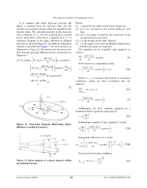
                  It  is  assumed  that  under  injection  pressure,  the   Where:
                slurry  is  injected  from  the  injection  hole  into  the   (i)   r represents the radius of the slurry spread (m).
                fracture and undergoes planar radial flow parallel to the   (ii)    Δr is the increment of the spread radius per unit
                fracture  plane. The  injection  pressure  at  the  injection   time.
                hole is denoted as P , and the scouring force exerted   (iii)   Δθ  is  the  angle  formed  by  the  increment  of  the
                                   0
                by the water flow on the slurry is denoted as P . 33,34  A   spread radius per unit time.
                                                          w
                schematic  diagram  of  the  slurry  diffusion  in  inclined   (iv)   ρ is the density of the slurry (kg/m ).
                                                                                                       3
                fractures is shown in Figure 11. An arbitrary differential   (v)    α is the angle of the crack inclination; higher-order
                element is selected from Figure 11 for stress analysis, as   infinitesimal terms are neglected.
                illustrated in Figure 12. The formula for the power-law   The  equation  can  be  simplified  and  organized  as
                fluid fracture grouting diffusion model is presented in   follows:
                Equation I:                                            d   dP P


                                       dP P  w                               w    g sin                    (II)
                 PP  w  r   z     PP  w     r  r    z   dz  dr
                                                        r

                                         dr                        With respect to z, integration yields:

                                     dP  P   r       d


                                PP      w     rz     z          dP P w       z C              (III)

                                  w
                                       dr    2         dz              dr     g sin     1
                            r r
                                     r

                                           r    gsinn rz
                                  2                                    Where  C   is  a  constant  determined  by  boundary
                                                                               1
                              r    r   r                   conditions,  which  are  then  substituted  into  the
                                          
 0
                                  2                                 equation.
                                                              (I)      du
                                                                             0  C  0                          (IV)
                                                                                    1
                                                                       dz  z0


                                                                           dP P
                                                                              w    g sin   z              (V)

                                                                              dr
                                                                       Additionally,  the  flow  variation  equation  for  a
                                                                    Newtonian fluid is generally expressed as:
                                                                            du   n
                                                                         k                                   (VI)
                                                                            dz
                                                                       Substituting Equation VI into Equation V yields:
                Figure  11.  Schematic  diagram  illustrating  slurry


                diffusion in inclined fractures                           du  n   dP P
                                                                                       w
                                                                       k                g sin 
  z       (VII)
                                                                          dz      dr
                                                                       Integration with respect to z yields:
                                                                                                   1


                                                                         n   1    dP P          n    n1
                                                                                      w
                                                                    u                 g sin 
   z   n   C    (VIII)

                                                                                                            2

                                                                        n 1   k    dr
                                                                       Based on the boundary conditions:
                                                                                           n1
                                                                                         b
                Figure 12. Stress analysis of a slurry element within   u  b 0  C       n                 (IX)
                an inclined fracture                                     z 2     2
                                                                                         2
                Volume 22 Issue 5 (2025)                       225                           doi: 10.36922/AJWEP025210162
   226   227   228   229   230   231   232   233   234   235   236