Page 82 - AJWEP-22-6
P. 82

Heidarnejad, et al.

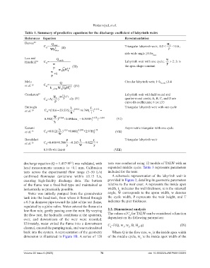
                 Table 1. Summary of predictive equations for the discharge coefficient of labyrinth weirs
                 References  Equation                                          Recommendation
                 Darvas 20       Q                                                                       H
                            C=     max                                         Triangular labyrinth weir; 0.2 ≤  T  ≤  0.6 ;
                              d    2   (II)
                                Wh                                                                        P
                                   max
                                                                               side wide angle ≥0.8α
                                                                                                max
                 Lux and            Q                                                                    w
                 Hinchliff 21  C=     cycle                                    Labyrinth weir with one cycle;   >  2 ; k is
                              d
                                  w                                                                      P
                                              (III)                            the apex shape constant
                                  P  wgH   1.5
                                 w         T
                                   +k
                                 P
                 Melo                 Q                                        Circular labyrinth weir; 1≤k θ-CW  ≤1.4
                 et al.  22  C=             1.5 (IV)
                              d
                                k    W 2gH
                                 ¸-CW       T
                 Crookston 23                                                  Labyrinth weir with half-round and
                                          ))
                                  H T  (B(  H T C  (V)                         quarter-round crests; A, B, C, and D are
                            C=A(     )  P   +D
                              d
                                   P                                           curve-fit coefficients; 6 ≤α ≤35
                 Emiroglu                                                      Triangular labyrinth weir with one cycle
                 et al.  24  C=(18.6 23.535[−  d  L 0.012 +6.769[  L 0.112  −
                                               ]
                                                           ]
                                             B            l
                                  W 4.024                 2.155 − 1.431   (VI)
                             0.502(  )   +0.0094sin¸ −  0.393Fr 1  )
                                   y 1
                 Karami               y                                        Asymmetric triangular with one cycle
                 et al.  25  C=0.012(  1 − 2.5  +0.881r ¸ 0.248  +2.97Fr 1.79  (VII)
                                        )
                                                           2
                              d
                                     W
                 Bonakdari                P        L       L                   Triangular labyrinth weir
                 et al.  26  C=0.466+0.388  − 0.183  − 0.022  +
                              d
                                          y       W        y
                            0.31Fr+0.12sinθ                                       (VIII)

                discharge equation (Q = 1.417⋅H ) was validated, with   tests was conducted using 12 models of TALW with an
                                             2.5
                head measurements accurate to ±0.1 mm. Calibration   expanded middle cycle. Table 3 represents parameters
                tests  across  the  experimental  flow  range  (5–50  L/s)   included for the tests.
                confirmed  flowmeter  deviations  within  ±0.15  L/s,   A schematic representation of the labyrinth weir is
                ensuring  high-fidelity  discharge  data.  The  bottom   provided in Figure 2, detailing its geometric parameters
                of  the  flume  was  a  fixed-bed  type  and  maintained  as   relative to the weir crest. A represents the inside apex
                horizontally as practically possible.               width, t  indicates the wall thickness, α is the sidewall
                                                                           w
                  Water  was initially  pumped from the groundwater   angle,  W corresponds to the apron width, w denotes
                tank into the head tank, from where it flowed through   the cycle width, P represents  the weir height, and  T
                a 0.3 m diameter pipe toward the inlet of the test flume,   indicates the pier thickness.
                regulated by a globe valve. Water entered the flume at a
                low flow rate, gently passing over the weir. By varying   2.2. Dimensional analysis
                the flow rate, the hydraulic conditions at the upstream,   The values of C  for TALW can be considered a function
                                                                                  d
                over, and downstream  of the  weir  were  recorded.   dependent on the following parameters:
                Ultimately, water exited the flume into a downstream   C =F(Q, w , w , B, H , g)                 (IX)
                channel, entered the pumping tank, and was recirculated   d   1  2     d
                back into the system. A representation of the geometry   Where Q is the flow rate, w  is the inside apex width
                                                                                               1
                dimension is illustrated in Figure 1B. A series of 120   of the middle cycle, w  is the inside apex width of the
                                                                                        2


                Volume 22 Issue 6 (2025)                        76                           doi: 10.36922/AJWEP025120081
   77   78   79   80   81   82   83   84   85   86   87