
Page 16 - IJB-3-2
P. 16
Directed self-assembly software for single cell deposition
before and after each transfer, distance between the sub- waypoints can be loaded into the waypoint list widget
strate and ribbon, and more. This data is being used as and used to repeatedly reposition the ribbon to areas of
“printing metadata” towards creating smarter printing interest, or they can be converted into a printing program
systems that learn from each failed transfer on their own that automates the laser firing, ribbon, and substrate
using machine vision and machine learning, with the motion. In addition, enabling machine vision to identify
goal of optimizing and accelerating LDW. each cell on a ribbon is currently being implemented
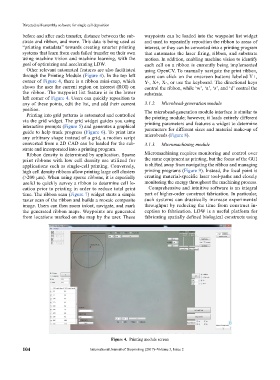
Other relevant automated features are also facilitated using OpenCV. To manually navigate the print ribbon,
through the Printing Module (Figure 4). In the top left users can click on the onscreen buttons labeled Y+,
corner of Figure 4, there is a ribbon mini-map, which Y-, X+, X-, or use the keyboard. The directional keys
shows the user the current region on interest (ROI) on control the ribbon, while ‘w’, ‘a’, ‘s’, and ‘d’ control the
the ribbon. The waypoint list feature is in the lower substrate.
left corner of Figure 4. Users can quickly reposition to
any of these points, edit the list, and add their current 3.1.2. Microbead-generation module
position. The microbead-generation module interface is similar to
Printing into grid patterns is automated and controlled
via the grid widget. The grid widget guides you using the printing module; however, it loads entirely different
printing parameters and features a widget to determine
interactive prompts (Figure 5) and generates a graphical parameters for different sizes and material make-up of
guide to help track progress (Figure 6). To print into
any arbitrary shape instead of a grid, a motion script microbeads (Figure 8).
converted from a 2D CAD can be loaded for the sub- 3.1.3. Micromachining module
strate and incorporated into a printing program.
Ribbon density is determined by application. Sparse Micromachining requires monitoring and control over
print ribbons with low cell density are utilized for the same equipment as printing, but the focus of the GUI
applications such as single-cell printing. Conversely, is shifted away from navigating the ribbon and managing
high cell density ribbons allow printing large cell clusters printing programs (Figure 9). Instead, the focal point is
(>200 µm). When using sparse ribbons, it is especially creating material-specific laser tool-paths and closely
useful to quickly survey a ribbon to determine cell lo- monitoring the energy throughout the machining process.
cation prior to printing in order to reduce total print Comprehensive and intuitive software is an integral
time. The ribbon scan (Figure 7) widget starts a simple part of higher-order construct fabrication. In particular,
raster scan of the ribbon and builds a mosaic composite such systems can drastically increase experimental
image. Users can then zoom in/out, navigate, and mark through put by reducing the time from construct in-
the generated ribbon maps. Waypoints are generated ception to fabrication. LDW is a useful platform for
from locations marked on the map by the user. These fa bri cating spatially defined biological constructs using
Figure 4. Printing module screen
104 International Journal of Bioprinting (2017)–Volume 3, Issue 2