
Page 480 - IJB-10-3
P. 480
International Journal of Bioprinting Stretchable scaffold for modeling fibrosis
Table 1. Equations for stiffness computation for a single beam element, using the elastic line equation under S.-L.B. and C.B.
approximations
Approximation type Equation for stiffness calculation
2
I
S-L.B. K ij SLB = 3 EAI L⋅ 3/( (sin()α 2 + AL cos( )))α 2
2
C.B. K ij CB = 12 EAI R⋅ 3/( ( I +π AR ⋅ 3( π − 8)))
Abbreviations: A: Cross-section area; alfa: Angle between the beam and vertical direction; C.B.: Curved beam; E: PCL Young’s Modulus;I: Moment of
inertia associated with the cross section; L: Straight beam length;R: Curvature radius of curved beam; S-L.B.: Straight-line beam.
A fixed support boundary condition of constrained 2.4. Fabrication of poly(ε-caprolactone) scaffolds
displacement was imposed on a scaffold length Based on the aforementioned mesh design, PCL scaffolds
corresponding to one unit cell length along the x-axis on were produced through MEX using a commercially
one scaffold end, limiting both translational and rotational available 3D printer (ROKIT Invivo 3D Printer Premium,
degrees of freedom (Figure 4). An external load, in the ROKIT Healthcare, Korea). Different sizes of PCL scaffolds
form of an imposed displacement, was applied to one were fabricated for structural and FEM analyses and
unit cell length on the free side of the scaffold, simulating mechanical tests: 6 × 4.5 mm with thickness of 0.3 mm for
2
the action of a tensile force to stretch the scaffold along cell tests; 14 × 4.5 mm with thickness varying according
2
the x-direction. A central unconstrained scaffold portion to the number of layers (from two to eight layers). PCL
with a total length of 1.5 unit cells was allowed to undergo pellets were loaded in a heated print head and melted at
deformation, representing the effective tested specimen. 100 °C. By applying compressed air with a pressure of
The imposed displacement along the x-direction (same 550 kPa, filaments were extruded through a nozzle with
as the F application) was 0.5 mm under the hypothesis of a diameter of 200 µm. The distance between the nozzle
linear elastic deformation. Stiffness was calculated as the and the printing bed was customized through a G-code to
ratio between force and displacement (Equation 1). achieve suitable print quality and resolution.
To optimize the accuracy of FEM results and 2.5. Preparation of photocurable gelatin
computational requirements for the simulations, a FEM methacryloyl hydrogels
mesh convergence study was performed by varying the GelMA prepolymer solution was prepared at three different
refinement of the mesh during solution estimation. As the concentrations (5, 7, and 10% w/v) in FGM-3 and stirred at
scaffolds were subjected to previously described boundary 50 °C in dark conditions for 1 h. LAP was added (0.5% w/v)
conditions, tensile force acting on a single beam was to the GelMA prepolymer solution and stirred for 15 min
computed using an increasing number of nodes. at 50 °C. Different volumes of GelMA solutions (30–300
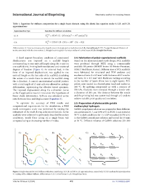
Figure 3. Single elements for total stiffness evaluation considering: (A) C.B. and (B) S-L.B. approximations, respectively. (C) 2D mesh model approximation
to a spring with a defined stiffness. Abbreviations: C.B.: Curved beam; S-L.B.: Straight-line beam.
Volume 10 Issue 3 (2024) 472 doi: 10.36922/ijb.2247