
Page 85 - IJB-6-3
P. 85
Yusupov, et al.
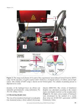
Figure 3. The image and scheme of the part of the experimental laser-induced forward transfer (LIFT)
setup. On the top panel, (1) galvo scanner with F-theha lens, (2) digital camera, (3) ribbon, and (4) light
source. The scheme of LIFT setup is shown on the bottom panel. The scheme of printing process is
depicted in the circle.
intensity of the hydrogel layer on ribbon was (Huvitz HRM-300). The volume of transferred
estimated gravimetrically using Adventurer Pro droplets was calculated according to the contact
AV114C (Ohaus, USA). angles and droplet diameter on the acceptor plate
2.4 Measuring droplet sizes (Figure 2). The static contact angles of hydrogels
were determined by the method of a sessile
The size of the transferred hydrogel microdroplets drop using an ACAM D-3 goniometer (APEX
was measured using a direct optical microscope Instruments, India).
International Journal of Bioprinting (2020)–Volume 6, Issue 3 81