
Page 85 - IJB-7-4
P. 85
Alrashoudi, et al.
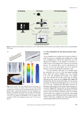
Figure 4. Schematic demonstration of the process used to fabricate the cassettes printed using material extrusion and vat polymerization
3D printing.
A B 3.3. FEA simulation for the final iteration of the
cassette
As the simulation was conducted on the same software, it
made the process of changing and modifying the design
more straightforward. During this experiment, we have
C E F changed the thickness of the dipstick several times to
reduce the use of any unnecessary material in the printing
process. We concluded that a cassette with thickness of
0.8 mm can be used and printed, and is the minimum
thickness needed considering the simulation result.
The mass applied on the edge of the cassette during
the simulation was set to be twice the normal handling
D force, where the normal handling force was assumed
to be 2.5N. The assumption and location of the applied
force were selected based on the actual state of a person
applying pressure using one hand (Figure 5D). Figure 5E
illustrates the dipstick cassette deformation for the pressing
simulation. The maximum deformation value was observed
to be 13.4 mm. Comparing the deformation result to the
Figure 5. (A and B) CAD of the dipstick housing unit design. (C) dimension of the model, the value range of the deformation is
CAD of the housing unit design with the bed pressing locking acceptable. Figure 5F illustrates the von Mises distribution
mechanism for securing the bed, the dipstick housing unit was 3D of stress in the pressing simulation of the dipstick. From this
printed using vat photopolymerization. (D) The assumption and result, it can be seen that the maximum stress of von Mises
location of the applied force used in the simulation. (E) Simulation
of the displacement for the dipstick cassette measured in mm when was 69.2 MPa. This is slightly lower than the yield strength
5 N force was applied. (F) Simulation of the von Mises stress of the material used in 3D printing which was approximately
measured in MPa on the dipstick cassette when 5 N force was 70 MPa. Under these conditions, the results suggest that our
applied. dipstick design will tolerate the expected use.
International Journal of Bioprinting (2021)–Volume 7, Issue 4 81