
Page 299 - IJB-9-4
P. 299
International Journal of Bioprinting Design and biomechanical analysis of porous tantalum prostheses
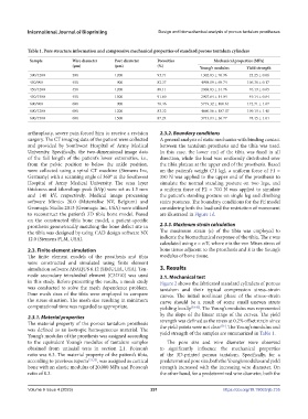
Table 1. Pore structure information and compressive mechanical properties of standard porous tantalum cylinders
Sample Wire diameter Pore diameter Porosities Mechanical properties (MPa)
(μm) (μm) (%) Young’s modulus Yield strength
300/1200 300 1200 93.71 1302.83 ± 76.96 23.25 ± 0.06
450/900 450 900 82.37 4998.09 ± 69.74 106.36 ± 0.17
450/1200 450 1200 88.11 2968.83 ± 31.76 76.19 ± 0.65
450/1500 450 1500 91.60 2907.64 ± 14.04 49.14 ± 0.64
600/900 600 900 76.46 5719.32 ± 100.61 172.71 ± 1.67
600/1200 600 1200 83.32 4660.56 ± 187.07 109.19 ± 1.40
600/1500 600 1500 87.24 3743.04 ± 36.77 78.45 ± 1.01
arthroplasty, severe pain forced him to receive a revision 2.3.2. Boundary conditions
surgery. The CT imaging data of the patient were collected A general analysis of static mechanics with binding contact
and provided by Southwest Hospital of Army Medical between the tantalum prosthesis and the tibia was used.
University. Specifically, the two-dimensional image data In this case, the lower end of the tibia was fixed in all
of the full length of the patient’s lower extremities, i.e., direction, while the load was uniformly distributed over
from the pelvic position to below the ankle position, the tibia plateau at the upper end of the prosthesis. Based
were collected using a spiral CT machine (Siemens Inc, on the patient’s weight (71 kg), a uniform force of F1 =
Germany) with a scanning angle of 360° at the Southwest 350 N was applied to the upper end of the prosthesis to
Hospital of Army Medical University. The scan layer simulate the normal standing posture on two legs, and
thickness and kilovoltage peak (kVp) were set as 1.5 mm a uniform force of F2 = 700 N was applied to simulate
and 140 kV, respectively. Medical image processing the patient’s standing posture on single leg and climbing
software Mimics 20.0 (Materialise NV, Belgium) and stairs postures. The boundary conditions for the FE model
Geomagic Studio 2013 (Geomagic Inc, USA) were utilized considering both the load and the restriction of movement
to reconstruct the patient’s 3D tibia bone model. Based are illustrated in Figure 1d.
on the constructed tibia bone model, a patient-specific
prosthesis geometrically matching the bone defect site in 2.3.3. Maximum strain calculation
the tibia was designed by using CAD design software NX The maximum strain (ε) of the tibia was employed to
12.0 (Siemens PLM, USA). indicate the biomechanical response of the tibia. The ε was
calculated using ε = σ/E, where σ is the von Mises stress of
2.3. Finite element simulation bone tissue adjacent to the prosthesis and E is the Young’s
The finite element models of the prosthesis and tibia modulus of bone tissue.
were constructed and simulated using finite element
simulation software ABAQUS 6.12 (SIMULIA, USA). Ten- 3. Results
node secondary tetrahedral element (C3D10) was used 3.1. Mechanical test
in this study. Before presenting the results, a mesh study Figure 2 shows the fabricated standard cylinders of porous
was conducted to solve the mesh dependence problem. tantalum and their typical compression stress–strain
Four mesh sizes of the tibia were employed to compare curves. The initial nonlinear phase of the stress–strain
the stress situation. The mesh size resulting in minimum curve should be a result of some small uneven struts
computational time was regarded as appropriate. yielding locally [33-35] . The Young’s modulus was represented
by the slope of the linear range of the curves. The yield
2.3.1. Material properties strength was defined as the stress at 0.2% offset strain since
The material property of the porous tantalum prosthesis the yield points were not clear . The Young’s modulus and
[36]
was defined as an isotropic homogeneous material. The yield strength of the samples are summarized in Table 1.
Young’s modulus of the prosthesis was assigned according
to the equivalent Young’s modulus of tantalum samples The pore size and wire diameter were observed
obtained from uniaxial tests in section 2.1. Poisson’s to significantly influence the mechanical properties
ratio was 0.3. The material property of the patient’s tibia, of the 3D-printed porous tantalum. Specifically, for a
according to previous reports [31,32] , was assigned as cortical predetermined pore size, both the Young’s modulus and yield
bone with an elastic modulus of 20,000 MPa and Poisson’s strength increased with the increasing wire diameter. On
ratio of 0.3. the other hand, for a predetermined wire diameter, both the
Volume 9 Issue 4 (2023) 291 https://doi.org/10.18063/ijb.735