
Page 27 - MSAM-2-3
P. 27
Materials Science in Additive Manufacturing Cast and 3D-printed fiber orientations
l
2 f sin
Pz(, ) when arcsin z
z
l 2
f
2 4 arccos
l f 2 sin
(II)
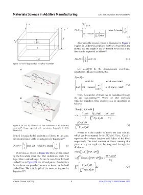
Afterward, the second region is illustrated in Figure 1
(region 2). Under this condition, the fiber is free within the
matrix, and the length of the arc formed by the end of the
fiber can be expressed as follows :
[9]
l
Pz(, ) 2 f sin 2 (III)
Figure 1. Divided regions of 1D boundary constraint.
A Let w=z/(l/2) be the dimensionless coordinate;
f
Equations I–III can be combined as
Pw,
sin 2 w 1 or w sin
w
(IV)
sin 2 4 arccos w
1 and w
sin
sin
Then, the number of fibers can be calculated through
[12]
B the arc circumference . When the fiber intersects
with the boundary, fiber numbers can be quantified as
follows:
Num z, d
,
l cos Pz, d ZV cos
N 2 f f
2 2 Pz, d r 2 f
0
Pw , d
Figure 2. (A and B) Schematic of fiber orientation in 1D boundary 2 d (V)
constraint . Image reprinted with permission, Copyright © 2017, 0 Pw ,
[9]
Elsevier Ltd.
Where N is the number of fibers per unit volume,
formed through the left endpoints of fibers. In this case, which can be computed by N=ZV /πl r . Here, V and r f
2
f f
f
f
the circumference of the locus is given by Equation I : represent the volume fraction and radius of the fiber,
[9]
respectively. The total number of fibers crossing this
l z plane at a given angle can be integrated through the
Pz(, ) f sin 2 when arcsin (I)
2 l f 2 thickness:
,
,
Otherwise, as shown in Figure 2B, fibers are restrained Num 0,Z d
by the boundary when the fiber inclination angle θ is Z 2 Num ,z d 2ZV f cos
,
larger than a critical angle. As can be seen from the bold 2 0 dz rr 2
dashed line in Figure 2B, the left endpoints of such fibers f
form a locus composed of two arcs, as shown by the bold Zl f Pw, d
dashed line. The total length of the two arcs is given by 0 2 Pw, d dw (VI)
Equation II : 0
[9]
Volume 2 Issue 3 (2023) 3 https://doi.org/10.36922/msam.1603