
Page 71 - MSAM-2-3
P. 71
Materials Science in Additive Manufacturing Additive manufacturing of SiC composite
PETG underwent partial decomposition to generate axes due to the thermal mismatch phenomenon with the
more pyrolyzed carbon, which, on the one hand, helps to fibers .
[45]
protect carbon fibers from corrosion in the subsequent PIP
process, and, on the other hand, increases the content of 3.2.2.2. C /SiC (PLA)
f
impure C elements in the final C /SiC products. The first cycle of PIP is the point at which the green parts
f
After the completion of pre-carbonization, the porous specimen is transformed from a resin-based composite
to a ceramic-based composite. Figure 16 shows the
green part specimens were impregnated with the precursor micrographs of the specimen after undergoing the first-
again, followed by curing and first-cycle pyrolysis, at cycle PIP treatment. Compared with Figure 5, Figure 16A
which time the SiC phase was generated for the first time shows that the resin matrix in the specimen was almost
in the specimen. Based on Figure 14C and D as well as completely decomposed, and the impregnated space left
Figure 15D–F, a large amount of SiC phase was generated behind by the previous macroscopic hole became a large,
on the surface of the specimen compared to the specimen collapsed SiC phase. Figure 16B shows the cross-section
after the pre-carbonation treatment, and large portions of of the specimen, which was cut by scissors. It can be seen
the SiC phase produced cracks perpendicular to the fiber that the resin-fiber-resin multilayer structure in the green
part specimens was left with only fiber layers parallel and
A B perpendicular to the cross-section, thus leaving a large
number of pores, which explains the significant increase
in apparent porosity and the significant decrease in
bulk density of the specimen after the first cycle of PIP
treatment. Figure 16C shows the surface of the specimen,
which shows that large thin planes of SiC phase was formed
on the surface of the specimen, and the large SiC phase was
C D divided into many small areas by many cracks along the
direction perpendicular to the fiber axis. This is caused by
several factors: (i) a large number of small molecules escape
from the PCS during the pyrolysis process, resulting in a
large volume shrinkage of the resulting ceramic product;
(ii) the PIP process is accompanied by a large temperature
difference between high and low temperatures; and (iii)
the thermal expansion coefficient between the generated
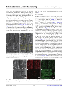
Figure 14. Scanning electron microscope observation of polyethylene SiC phase and the carbon fiber does not match, resulting
terephthalate glycol (PETG)-based green parts. (A and B) Pre-carbonized
[45]
PETG-based green parts. (C and D) PETG-based green parts in the first- in cracking . Figure 16D shows that the bond between
cycle precursor infiltration pyrolysis. the fibers and the matrix is very strong, forming a strong
A B C
D E F
Figure 15. Energy dispersive spectroscopy surface scan results of polyethylene terephthalate glycol (PETG)-based green parts. (A) Pre-carbonized PETG-
based green parts. (D) PETG-based green parts in the first-cycle precursor infiltration pyrolysis. (B and E) C element distribution. (C and F) Si element
distribution.
Volume 2 Issue 3 (2023) 10 https://doi.org/10.36922/msam.1604