
Page 32 - MSAM-4-1
P. 32
Materials Science in Additive Manufacturing TPMS for perfect sound absorption
Table 3. Design parameters of graded primitive structures
Specimen Size of a unit cell on the Size of a unit cell on Thickness of porous Linear
incident face (mm) rigid face (mm) structure (mm) function
GP-12 mm-Ⅰ 2 4 12 1
GP-12 mm-Ⅱ 4 2 12 s 6 * z 2
GP-18 mm-Ⅰ 2 4 18 1
GP-18 mm-Ⅱ 4 2 18 s 9 * z 2
GP-24 mm-Ⅰ 2 4 24 1
GP-24 mm-Ⅱ 4 2 24 s * z 2
12
GP-30 mm-Ⅰ 2 4 30 1
GP-30 mm-Ⅱ 4 2 30 s 15 * z 2
Multicavity-GP-Ⅰ 2 4 12+18+24+30 N/A
Multicavity-GP-Ⅱ 4 4 12+18+24+30 N/A
Note: The thickness of multicavity-GP-I and multicavity-GP-II is based on the combined thickness of Design models for multicavity structures.
Abbreviation: GP: Graded primitive; N/A: Not available.
A B
C
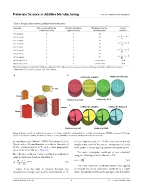
Figure 2. Design models for multicavity structures. (A) Design method for multicavity triply periodic minimal surface (TPMS) structures. (B) Design
models of multicavity TPMS structures (top view). (C) Design models of multicavity TPMS structures (bottom view).
an impedance tube (SW4661; BSWA Technology Co. Ltd., j is the imaginary part, √-1, l is the distance from the test
China) with a 29 mm diameter at a relative humidity of sample to the center of the nearest microphone (m), and s
68.2%, a temperature of 27℃, and a wave propagation is the center-to-center spacing between microphones (m).
speed in the air of 347 m/s (Figure 6).
The sound absorption coefficient α was calculated
The reflection coefficient R with a rigid back was calculated using the following function (Equation Ⅵ):
using the following function (Equation V):
−
He − jks α = −1 R 2 (Ⅵ)
R = e j 2(kl + )s (V)
e jks − H
The noise reduction coefficient (NRC) was applied
where H is the ratio of pressure between two to evaluate the sound absorption capability as a single
microphones, k is equivalent to 2pf/c (wavenumber [m ]), index. We calculated NRC as the average of the absorption
-1
Volume 4 Issue 1 (2025) 5 doi: 10.36922/msam.5737