
Page 140 - MSAM-4-3
P. 140
Materials Science in Additive Manufacturing Sunflower-inspired microwave-absorbing metastructure
A B
C D
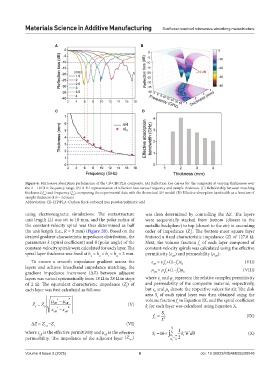
Figure 6. Microwave absorption performance of the CB-CIP/PLA composite. (A) Reflection loss curves for the composite at varying thicknesses over
the 2 – 18 GHz frequency range. (B) A 3D representation of reflection loss versus frequency and sample thickness. (C) Relationship between matching
thickness (d ) and frequency (f ), comparing the experimental data with the theoretical λ/4 model. (D) Effective absorption bandwidth as a function of
m
m
sample thickness (1.0 – 4.0 mm)
Abbreviation: CB-CIP/PLA: Carbon black-carbonyl iron powder/polylactic acid
using electromagnetic simulations. The metastructure was then determined by controlling the ΔZ. The layers
unit length (L) was set to 18 mm, and the polar radius of were sequentially stacked from bottom (closest to the
the constant-velocity spiral was thus determined as half metallic backplane) to top (closest to the air) in ascending
the unit length (i.e., R = 9 mm) (Figure 2B). Based on the order of impedance (Z ). The bottom-most square layer
i
desired gradient characteristic impedance distribution, the featured a fixed characteristic impedance (Z) of 127.8 Ω.
parameters k (spiral coefficient) and θ (polar angle) of the Next, the volume fraction f of each layer composed of
c
constant-velocity spirals were calculated for each layer. The constant-velocity spirals was calculated using the effective
spiral layer thickness was fixed at h = h = h = h = 2 mm. permittivity (ε ) and permeability (μ ):
1 2 3 4 eff eff
To ensure a smooth impedance gradient across the ε = ε f +(1−f )ε (VII)
c c
eff
c
layers and achieve broadband impedance matching, the μ = μ f +(1−f )μ 0 (VIII)
gradient impedance increment (ΔZ) between adjacent eff c c c 0
layers was varied systematically from 18 Ω to 28 Ω in steps where ε and μ represent the relative complex permittivity
c
c
of 2 Ω. The equivalent characteristic impedance (Z ) of and permeability of the composite material, respectively,
i
each layer was first calculated as follows: but ε and μ denote the respective values for air. The disk
0
0
area S of each spiral layer was then obtained using the
i
volume fraction f in Equation IX, and the spiral coefficient
c
Z Z 0 eff eff (V) k for each layer was calculated using Equation X.
i
eff eff i
f = S i (IX)
c L 2
ΔZ = Z −Z (VI)
i+1 i
R i 1
where ε is the effective permittivity and μ is the effective S 16 R i k i k (X)
d
2
2
eff
eff
permeability. The impedance of the adjacent layer (Z ) i k i 2 i
8
i+1
Volume 4 Issue 3 (2025) 6 doi: 10.36922/MSAM025220048