
Page 11 - ESAM-1-2
P. 11
Engineering Science in
Additive Manufacturing AM-CFRP structures for EMWA properties
35
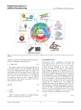
Figure 2. Electromagnetic wave loss with various microwave mechanisms. Copyright © 2021 The Chinese Ceramic Society. Reproduced with permission
of Elsevier.
magnetic conductor moving inside a fluctuating magnetic 2.6. Interference loss
field, may be calculated using Equation IV: Interferometric loss is dependent on the idea that
C =≈ 2πµ µ σD f (IV) electromagnetic waves interfere with one another and
’2
2
o o cancel each other out, giving rise to a zero net return.
By creating a magnetic field in the opposite direction of It places particular demands on the actual material.
the initial alternating current (AC) field, the eddy current Refraction and reflection occur when an electromagnetic
protects the magnetizing field inside the magnet and beam traveling in parallel hits a material’s surface. An
exponentially reduces the strength of the AC field, which outgoing wave is produced from the surface of the material
ultimately results in the skinning effect. The magnetic loss by the lower metal plate reflecting the incident component
factor, which is based on the ratio of µ′ to µ′′, indicates of the electromagnetic wave. The propagation direction of
the capacity of a medium to retain a magnetic field. The the wave stays constant. Based on the absorbing material’s
skinning depth of the material and magnetic loss factor quarter wavelength, the absorption principle states that
can be expressed as follows: these waves cancel each other at this point, significantly
lowering the total reflected wave. The entering and
'' outgoing waves have a phase difference of precisely 180°
tgδ = (V) since the thickness of the absorbing material is equal to a
'
quarter wavelength. To enable better EMA characteristics
and cause the incident and reflected waves in the material
2 ρ to be out of phase, the thickness t is set to be an odd
δ = (VI)
ωµσ multiple of the quarter wavelength in the material.
where δ is penetration depth, ω is angular frequency, tn m (VII)
ω=2πf, ρ is resistivity, and σ is conductivity. 4
Volume 1 Issue 2 (2025) 5 doi: 10.36922/ESAM025160008