
Page 194 - IJB-10-2
P. 194
International Journal of Bioprinting Optimizing inkjet bioprinting
cell sedimentation, it has been reported to significantly The resistor vaporizes only a tiny portion of the ink
reduce cell viability from approximately 99% to around above it, typically between 20 and 100 nm (equivalent to
~75% after 50 min of stirring. Therefore, this approach 0.1% of the chamber height), forming numerous small
40
may not be suitable for certain types of cells that are more vapor bubbles. Importantly, this heating process does not
sensitive to mechanical stresses. lead to a temperature excursion or significantly impact
the cells within the chamber. These small vapor bubbles
44
3. Printing chamber rapidly coalesce into one large vapor bubble, with the
pressure inside the bubble reaching several MPa. As this
45
It is crucial to address the design and operation of the vapor bubble rapidly expands, it imparts momentum on
print chamber in bioprinting, as it has significant impact the surrounding liquid.
on various factors, including cell viability, number
of dispensed cells, and post-dispense cell phenotype. The liquid column on the inlet side of the TIJ resistor,
Specifically, we discuss the design and operation of TIJ which includes the cell reservoir, has a much larger mass
print chambers, PIJ print chambers, the cellular behavior than the downstream column (the outlet or nozzle side).
under shear forces, and the conditions experienced by cells Consequently, the downstream liquid is accelerated to a
within these print chambers. This is essential for ensuring much larger velocity than the upstream column, ultimately
successful and effective bioprinting processes and the ejecting the liquid out of the nozzle. After ejection, the vapor
fabrication of 3D-bioprinted tissue constructs. within the vapor bubble condenses, causing the bubble to
collapse. The capillary pressure created by the resulting
3.1. Overview of thermal and piezo meniscus pulls new liquid into the printing chamber,
printing chambers preparing it for another dispense cycle. The duration of the
The TIJ printing chamber typically comprises an ink dispense cycle is determined by the time it takes for the
supply inlet, a thin film resistor, and a nozzle, serving as meniscus to draw new liquid into the chamber, typically
the outlet for the ink (as shown in Figure 3). In its usual lasting between 20 and 1000 µs.
operation, a sub 40 V voltage pulse (1–10 µs) is applied The lifetime of the print chamber is influenced by
across the resistor. This pulse results in the rapid heating of several factors, including cavitation and kogation at the
the resistor surface, with a heat flux of the order of GW/m resistor surface, as well as cell lysis. In TIJ cavitation, the
2
8
and at a rate of ~10 K/s, raising the temperature to around collapsing vapor bubble generates a shock wave toward
300°C. 41,42 The primary purpose of this process is to induce the resistor, inducing stresses in the resistor material. This
43
uniform nucleation at the surface of the resistor. cyclic stress can lead to material fatigue and damage to
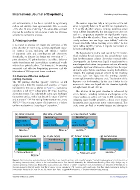
Figure 3. Schematic cross sections of typical thermal (a–c) and piezo (d–g) inkjet print chamber designs. Thermal inkjet designs vary in the position of
the heating element (resistor) relative to the location of the nozzle. This is mainly dictated by the fabrication methodology. Piezo inkjet designs vary in
chamber geometry, position and design of the piezo actuator, and presence of axillary components such as membranes. As deflection of the fluid due to
the piezo element is typically smaller than that of a vapor bubble, piezo inkjet (PIJ) chambers are typically larger than their inkjet counterparts, leading to
lower nozzle density on the print die. For PIJ, dashed lines depict exaggerated deformation of the piezo element during printing.
Volume 10 Issue 2 (2024) 186 doi: 10.36922/ijb.2135