
Page 374 - IJB-10-3
P. 374
International Journal of Bioprinting Multi-physical field control inkjet bioprinting
two parameters determined the size and duration of the the pulse width was set to 1.5 ms, the pressure increased
external force on the fluid, which affected the pressure field directly to the voltage amplitude. Therefore, it could be
and ultimately determined the diameters and velocities of inferred that the diameter and velocity of the microdroplet
the microdroplets. were directly proportional to the voltage amplitude. We
also simulated the relationship between pressure and pulse
Based on the above-mentioned control theory, we
conducted a simulation using piezoelectricity and fluid– width (Figure 3C). By converting acoustic pressure wave
oscillation problems into electrical oscillation problems,
structure interaction modules. To set the simulation the difficulty of process analysis and modeling can be
boundary conditions, we applied a back pressure of 970 Pa greatly simplified. During the process of analogy, the
38
at the entrance, and set the exit speed to 0. Additionally, we similarity between the physical processes of pressure
made the inner and outer walls of the piezoelectric ceramics release and capacitor discharge is used to liken the process
bipolar, with the inner wall grounded and the outer wall of pressure change to the process of capacitor charging
applied with driving voltage. The driving waveform is and discharging. 39,40 The present work also used the
presented in Figure 1A, with a voltage amplitude of 192 mathematical form of capacitor charging and discharging
V. We conducted simulations to investigate the effects of to express the changes in pressure, as defined by Equation
the voltage amplitude and pulse width. By controlling the III, which can be applied for piezoelectric inkjet printing.
voltage amplitude and pulse width, the deformation of the Experimental observation can solve the formula coefficient
piezoelectric ceramic and the change in pressure field at the when there is a change in the printing material or printhead
corresponding time were studied (Figure 3A). The driving structure (the formula derivation process is shown in the
wave controlled the vibration of the piezoelectric ceramic, Supplementary File),
and the piezoelectric ceramic controlled the internal
pressure field of the printhead through deformation. PAe= − ( tT/ ) (III)
Since the pressure at the nozzle was the most critical
factor for the formation of microdroplets, we used the where P, A, t, and T are pressure, coefficient, time,
simulation to obtain the relationship between the pressure and time constant, respectively. The change in pressure
at the nozzle and the voltage amplitude (Figure 3B). When followed the functional relationship of capacitance
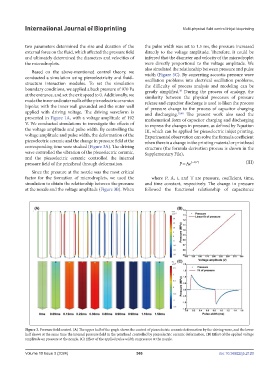
Figure 3. Pressure field control. (A) The upper half of the graph shows the control of piezoelectric ceramic deformation by the driving wave, and the lower
half shows at the same time the internal pressure field in the printhead controlled by piezoelectric ceramic deformation. (B) Effect of the applied voltage
amplitude on pressure at the nozzle. (C) Effect of the applied pulse width on pressure at the nozzle.
Volume 10 Issue 3 (2024) 366 doi: 10.36922/ijb.2120