
Page 251 - IJB-10-4
P. 251
International Journal of Bioprinting Cell viability in printing structured inks
were developed. These models considered the cartridge set, a pressure-based transient solver was employed to
and nozzle specifications for CFD simulations (Figure 2). calculate the solution, utilizing governing equations,
37
Properties of the equivalent homogeneous inks for including continuity, momentum, and energy equations.
both symmetric and core–shell inks were analyzed to Post-simulation results were imported into the CFD-Post
generate approximately the same fluid forces during the package for visual representation and quantitative analysis
printing processes. to evaluate the distribution of material phases at the nozzle
outlets, as well as fluid forces, including pressure, wall
2.6. Simulation method overview
To calculate the fluid forces affecting cell viability, a shear stress, and shear stress at material phase interfaces.
sequential approach encompassing pre-processing, solving, 2.7. Numerical simulation models
and post-processing was employed for CFD simulation. For fluid models, there are two categories corresponding to
The ANSYS Workbench software, version 2020R2, was used the printing of different structured inks and conventional
with Fluent as the solver and CFD-Post package as the post- printing. All fluid models were simplified due to their
processor. To enhance computational efficiency, the fluid inherent symmetry. The model corresponding to hepatic
models were simplified by means of symmetry. During the lobule analogue-like inks was simplified to 1/12 size, the
pre-processing phase, models for fluid analysis, designed in symmetric model was simplified to 1/2, while other models
Parasolid format, were imported into the Design Modeler were conventionally streamlined to 1/4. The respective 3D
module. Subsequently, the corresponding mesh models symmetric models were modeled, as illustrated in Figure
were generated through the Mesh module, with a focus on S2 (Supplementary File). For 2-symmetric inks, symmetric
both computational accuracy and time efficiency. Inlets, inks, and core–shell inks, the pink and green areas were
outlets, pipe walls, and symmetry planes were then defined constrained as ink 1 and ink 2, respectively. In other
for the subsequent solving phase. In the solving stage, cases, the pink, green, and blue-purple domains were all
the multiphase flow methodology in Fluent, using the constrained as ink 1, with the distinction in their regions
“Volume of Fluid” module and a laminar flow model, was being the involvement of cells. All gray planes and black
selected for structured inks-based methods. This choice planes indicate 3D symmetry planes for the respective fluid
was made because the materials used in the 3D printing of models. Domain in phase 1 corresponds to inlet 1, domain
structured inks maintain laminar flow within the printhead in phase 2 to inlet 2, and domain in phase 3 to inlet 3.
channels during the extrusion processes. Surface tension
30
modeling was implemented to capture interfaces between In the process of model meshing, smaller elements
different phases, and single-phase laminar flow models typically result in more accurate finite element modeling,
were chosen for simulating conventional printing involved as an increased number of mesh elements enhances
in comparative and equivalent analysis. Once material accuracy in calculating fluid behavior. However, this
properties were defined and boundary conditions were comes at the cost of higher computational resource,
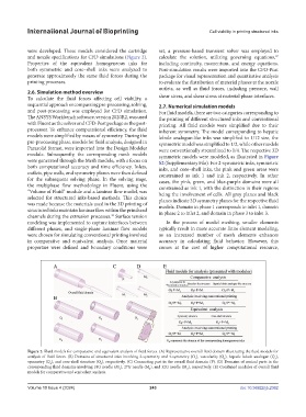
Figure 2. Fluid models for comparative and equivalent analysis of fluid forces. (A) Representative overall fluid domain illustrating the fluid models for
analysis of fluid forces. (B) Domains of structured inks involving 2-symmetry and 4-symmetry (O ), vascularity (Q ), hepatic lobule analogue (Q ),
1
2
3
symmetry (Q ), and core-shell structure (Q ), respectively. (C) Connecting part in the overall fluid domain (P). (D) Domains of conical parts in the
4
5
corresponding fluid domains involving 18G needle (M ), 27G needle (M ), and 32G needle (M ), respectively. (E) Combined modules of overall fluid
1
2
3
models for comparative and equivalent analysis.
Volume 10 Issue 4 (2024) 243 doi: 10.36922/ijb.2362