
Page 403 - IJB-10-4
P. 403
International Journal of Bioprinting Design of biofixed metamaterial bone plates and fillers
displacement transmission effect, and there was no to avoid loosening the filler after surgery and also to ensure
apparent gap at the contact interface of the resultant biological fixation after tissue ingrowth.
mixed-porous structure. Additionally, further
analysis of the mixed-porous structure revealed that 3.2.2. Design of the conformal femoral bone plate
the porosity was 79.93%, the average pore size was The segmented part of the bone was combined with
0.87 mm, and the surface area-to-volume ratio was the femur and imported into the 3-Matic Research 12.0
2.97. In summation, the mixed-porous structure software. The bone plate placement position was marked,
retained the high porosity and load-bearing capacity and the shape of the bone plate was outlined using the
of the diamond structure and the large surface area- brush marking tool. Thereafter, we smoothened the rough
to-volume ratio of the Split P structure. marked edge of the completed bone plate and divided the
3.2. Design of the personalized bone plate bone plate accordingly to establish a conformal bone plate
surface model that was saved in the STL file format. We
3.2.1. Reverse reconstruction and simulated then imported the bone plate surface model into the Inspire
osteotomy of femoral prosthesis software for solidification. The offset of the bone plate was
Bone injuries may occur in different areas for different thickened by 3 mm, and 3.5 mm screw fixation holes were
patients, and the bones may have complex geometric or created at the top of the bone plate, prior to assembly with
curved shapes. Hence, medical imaging (e.g., computed the femur and filler. Given that the linear arrangement of
tomography [CT] or magnetic resonance tomography screw holes would lead to stress concentration, we cross-
[MRT]) is commonly used to evaluate the bone structure
and injury location. This step is crucial in 3D reconstruction arranged the screw holes. It was observed that the bone plate
to increase the fit degree between the designed implant and matched well with the femur, and the fit was tight (Figure 7).
the affected site, lower the possibility of implant loosening, 3.3. Topological design optimization of bone plate
and improve the success rate of implant surgery. We used and filler
CT and nuclear magnetic resonance (NMR) to image the
affected site of the patients. 3.3.1. Simulation parameter settings for femoral bone
It is necessary to distinguish between cancellous and plate and filler
cortical bone to simulate the human skeleton. Due to the The assembled 3D structure (i.e., femoral bone/interlocking
complexity of human tissue, the internal grayscale value plate and filler with the original model) was saved in the
for the cancellous bone is generally too small to construct STP file format and imported into the Inspire software for
dense bone tissue using a mask, thereby requiring artificial simulation. Several load and constraint parameter settings
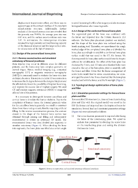
filling. In the reverse reconstruction process, the contour (Figure 8a) were addressed as follows:
closest to the shape of the femoral bone section was
obtained through erasing and filling and subsequently (i) The screw fixation parameter is required after fixing
reconstructed to obtain an optimized 3D model. The the holes of the interlocking plate. We opted to
reconstructed femur was then divided into segments to exclude this parameter by dividing the screw holes
simulate osteotomy (Figure 6). When dividing the bone on the interlocking plate and setting the division
into segments, the bone plate was tilted at a certain angle thickness to 2 mm.
Figure 6. Reverse reconstruction and simulated osteotomy of femoral prosthesis.
Volume 10 Issue 4 (2024) 395 doi: 10.36922/ijb.2388