
Page 408 - IJB-10-4
P. 408
International Journal of Bioprinting Design of biofixed metamaterial bone plates and fillers
plates are required. For this purpose, we designed a 3.5 wall thickness was 0.6 mm; and the printing temperature
mm diameter screw based on the standard specifications was 190°C (Figure 12a).
and test methods of ASTM F543-07 for metal medical Previous studies performed SLM at an inclined angle
bone screws. The screws were arranged according to of 45° for the fillers and bone plates to avoid the excessive
the fixed hole position to ensure the effectiveness of the use of supports. In addition, the solid surface could be
22
openings; the fixation holes were then closed, and the faced downward to facilitate the removal of supports and
arranged screws were imported for Boolean operations improve the surface quality of the printed part. After the
to complete the screw hole openings. The screw hole completion of the part placement, the machining risk
openings were adequate, and the bone plate was analysis in the Materialize Magics software identified
fixed successfully. machining risks occurring at the bottom and top of the
o
3.6. 3D printing of the femur, bone plate, and filler printed parts (Figure 12b). As an inclined angle of 45
was used for machining risk analysis, it was not necessary
3.6.1. Process of 3D printing the femur, bone plate, to add support to the top of the bone plate. Based on our
and filler experience, the bottom part of the printed structure could
The different placement methods and complexity of be densified due to greater downward force. Tree supports
the 3D-printed parts determine the cost of the printing are widely used for their easy removal, no damage to the
process and the quality of the final printed part. When suspended bottom surface after removal, high strength,
printing femoral prostheses with a plastic 3D printer, minimal support usage, and low stress concentration.
the substrate was optimized at an inclined angle of 15° We added tree supports based on the shape of the bone
to prevent excessive scan lines. In addition, the substrate plate and filler. The tree support parameters are as follows:
was preheated to 60° to prevent excessive temperature the top diameter of the trunk was 0.2 mm; the bottom
difference and warping deformation between the substrate diameter was 0.3 mm; the top diameter of the branches
and the formed femoral part. The processing parameter was 0.1 mm; and the bottom diameter was 0.2 mm. The
settings were as follows: the sliced layer thickness was 0.15 maximum number of branches on each trunk was five;
mm; the material was PLA; the filling density was 18%; the the minimum distance between connection points was 0.6
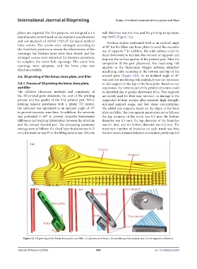
Figure 12. 3D printing of the femur, bone plate, and filler: (a) placement of femur; (b) machining risk analysis; and (c) tree support utilization.
Volume 10 Issue 4 (2024) 400 doi: 10.36922/ijb.2388