
Page 398 - IJB-10-4
P. 398
International Journal of Bioprinting Design of biofixed metamaterial bone plates and fillers
Table 2. Comparison of the elemental composition between mechanism and evaluated the performance of various
316L stainless steel powder and the ASTM A276 standard porous structures. In the simulation analysis of the porous
structures, the material parameters were set to mimic 316L
Element Elemental composition (%)
stainless steel (elastic modulus: 206 GPa; Poisson’s ratio:
316L stainless steel powder ASTM A276 standard 0.3), i.e., applying a 20 N point load on the top surface of
the porous structure and using total constraints on the
C <0.03 <0.03 bottom surface.
Mn <2.0 <2.0 We used the electronic universal testing machine
S <0.01 <0.03 GP-TS2000L to perform compression tests along the
Ni 12.5–13 10–14 longitudinal direction of the porous structure. The
Cu 0.50 0.75 compression displacement speed was set to 1 mm/min.
Si <0.75 <1.00 The computer automatically recorded and processed the
P <0.025 <0.045 load-displacement data to obtain a stress–strain curve.
After averaging the relevant stress–strain curve data,
Cr 17.5–18 16–18
the compressive strength was analyzed, and the elastic
Mo 2.25–2.5 2–3
modulus was obtained using the least-squares fit.
Fe Balance Balance
Reverse reconstruction and osteotomy guide for the
femoral prosthesis were performed using the Mimics
the particles were approximately 22 μm, and the average software. Physical modeling of the joint plate and filler
particle size was 28.5 μm. was performed using the 3-Matic Research 12.0 and
In the SLM process, nitrogen was used as the protective Inspire software, and the optimal design of the joint plate
gas; oxygen content was kept below 0.03%; the processing was determined using the Inspire software. Topology
laser power was 170 W; the scanning speed was 500 mm/s; optimization is a mathematical method that optimizes the
the scanning spacing was 60 µm; the processing layer distribution of materials within a given area based on given
thickness was 25 µm; the XY interlayer staggered scanning load conditions, constraints, and performance indicators.
strategy was used. It is a type of structural optimization and is determined
using the Rhinoceros software. Thereafter, the porous
2.3. Analytical methods curved structure of the bone plate was filled. We performed
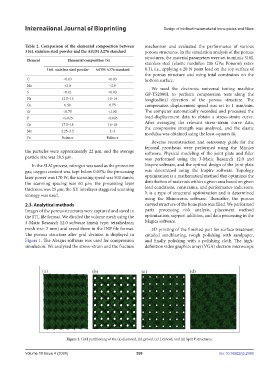
Images of the porous structures were captured and saved in parts processing risk analysis, placement method
the STL file format. We divided the volume mesh using the optimization, support addition, and data processing in the
3-Matic Research 12.0 software (mesh type: tetrahedron; Magics software.
mesh size: 2 mm) and saved them in the INP file format. 3D printing of the finished part for surface treatment
The porous structure after grid division is displayed in entailed sandblasting, rough polishing with sandpaper,
Figure 1. The Abaqus software was used for compression and finally polishing with a polishing cloth. The high-
simulation. We analyzed the stress–strain and the fracture definition video graphics array (VGA) electron microscope
Figure 1. Grid partitioning of the (a) diamond, (b) gyroid, (c) Lidinoid, and (d) Split P structures.
Volume 10 Issue 4 (2024) 390 doi: 10.36922/ijb.2388