
Page 10 - IJB-5-2
P. 10
Application of additive manufacturing technology in orthopedic medical implant-Spinal surgery as an example
The biomodel greatly assisted with the explanation to 4.2. Patient B
the child’s parents regarding the surgery planned and A 9 year old female, diagnosed with myelomeningocele
the associated risks involved, thereby, helped to obtain spina bifida (neurological deficit below T10) with severe
informed consent. collapsing T10-S1 due to the total absence of posterior
The surgeons reported that the addition of fixation to the
upper cervical spine had made the instrumented construct elements. The resulting kyphotic deformity was causing
more robust and had improved the deformity correction seating difficulties and the maintenance of the integrity
achieved by the procedure in addition to the decompression of the skin over the kyphotic deformity was becoming
and stabilization components. With the additional fixation challenging, with skin breakdown becoming more
frequent. It was considered that kyphectomy and posterior
points, the surgeon reported that the risk of requiring instrumented fusion would improve the quality and length
a revision procedure in the future was also less likely. of life. Preoperatively, the patient had PA and LAT sitting
Although the pedicle screw placement in the thoracic spine spine radiographs (Figure 6), thoracolumbar spine CT
was not optimum, they have held well to date, the patient’s with 3D reconstruction (Figure 7), and a biomodel was
neurological signs have improved and thereafter remained ordered (Figure 8).
stable, with no loosening or loss of correction now The surgical plan was to ideally perform a
10 months postoperative. Supine LAT and PA radiographs kyphectomy between two and five levels followed by
1 month after surgery and the most recent LAT view at deformity correction and stabilization with a posterior
10 months post-operative are shown in Figure 5.
instrumented fusion from the upper thoracic spine to the
pelvis; however, the thoracolumbar anatomy, especially
the thoracolumbar junction anatomy, remained
unclear. Having no posterior spinal elements to fix
A B C
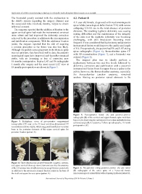
Figure 5. Post-operative lateral (A) and posterior-anterior
radiographs (B) of the cervical and upper thoracic spine with halo
brace in situ illustrating the instrumented correction and stabilization
Figure 3. Multiplanar views of pre-operative computerized
tomographic (CT) scan at the C2 level and three-dimensional CT achieved surgically for patient a. Follow-up radiographs, 10-month
reconstruction (lower right), which suggested insufficient vertebral postoperative (C).
bone in the posterior elements of the upper cervical spine for
posterior fixation (patient A). A B
Figure 4. Three-dimensional printed biomodel (sagittal, anterior,
and upper cervical close-up views) demonstrates that the anatomy
of the C2 laminae was of sufficient size to accept fixation posteriorly Figure 6. Pre-operative sitting posterior-anterior (A) and lateral
in addition to the previously planned fixation points in the base of (B) radiographs of the entire spine of a 9-year-old female
the skull and upper thoracic spine (patient A). (myelomeningocele spina bifida) with collapsing kyphosis (patient B).
6 International Journal of Bioprinting (2019)–Volume 5, Issue 2