
Page 11 - IJB-5-2
P. 11
Zhang, et al.
instrumentation into, alternative fixation points were 5. Surgical Tools and Guides
required. After receiving the biomodel, the anatomy
of the lower thoracic and lumbar spine was clear Since 2009, designing and printing guides for pedicle
and the decision was made with some confidence to screw placement has emerged as a new area of additive
proceed with the kyphectomy of L1-L3 followed by an manufacturing for spinal surgical planning, particularly
[11,12]
instrumented fusion from T3-pelvis (Figures 9 and 10). in the cervical spine . The anatomy in this region is
The biomodel also greatly assisted with the explanation quite compact and even more so in pediatric cases, with
to the child’s parents regarding the planned surgery delicate neural tissue in close proximity making precise
and the associated risks involved, thereby, helped to screw insertion of great importance. utilized additively
The earlier papers from Lu et al.
[11,12]
obtain informed consent. The patient recovered well, manufactured drill guides for two kinds of screw
and the parents reported that caring for their child was
much easier, as was her comfort when seated in her placement in the cervical spine. These plastic guides were
wheelchair. There was an added benefit of being able to placed directly in contact with the patient’s exposed bony
sleep supine for the 1 time in many years. There were anatomy in the operating room and used to insert screws
st
no longer any issues with skin integrity or pressure areas along predefined trajectories. The author reported that
over her spine. The fixation has remained stable with no this technique is highly accurate. Additionally, reduces
complications. both the surgery time and radiation exposure. These
A B
Figure 7. Sagittal views from pre-operative computerized
tomographic (CT) scan and three-dimensional CT reconstruction
(far right) of the thoracic and lumbar spine showing more anatomic
detail than radiographs of the deformity, but insufficient detail to
decide how many levels to remove and the precise fixation points
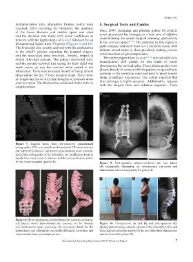
for the instrumentation (patient B). Figure 9. Post-operative anterior-posterior (A) and lateral
(B) radiographs illustrating the instrumented correction and
stabilization achieved surgically for patient B.
A B C
Figure 8. Three-dimensional printed biomodel (anterior, posterior,
and lateral views) demonstrates the anatomy of the thoracic Figure 10. Pre-operative (A and B) and post-operative (C)
and lumbosacral spine providing the necessary detail for the photographs showing cosmetic aspects of the deformity before and
kyphectomy and subsequent successful deformity correction and after surgical correction assisted by the use of the three-dimensional
instrumented fusion procedure patient. printed biomodel (patient B).
International Journal of Bioprinting (2019)–Volume 5, Issue 2 7