
Page 26 - IJB-6-2
P. 26
3D-printed splint for mallet finger injury
conducted with varying element sizes and model Table 1. Heat simulation analysis settings
that had <5% variation in maximum stress was Internal splint surface temperature (°C) 31.7
selected. W 10
Convection coefficient of air 2
2.5 Thermal heat analysis m ·K
Total heat generation of human body (W) 110
Using the four splints created, thermal analysis Average body surface area of human adult (m ) 2
2
of the prototypes was undertaken. The Static
Structural module in ANSYS used to test for A B
deflection and stress values were linked with
steady-state thermal module to link the data. The
internal face of each of the splints was selected
and set at 31.7°C, the temperature of the skin at
room temperature . The convection coefficient
[40]
of air at 22°C in free convection was selected
as 10 W/(m .K). The total heat generation of the
2
human body for this project is selected 110 W .
[41]
A heat flux was also created for the internal face
assuming that the average body surface area of
human adult is 2 m . Table 1 details the properties
2
calculated above.
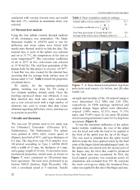
To clarify, for the topology-optimized Figure 7. A three-dimensional-printed dog-bone
splints, meshing was done for TO using a poly-lactic-acid sample (A) before, and (B) after
low element number, default mesh. Once the tensile test.
topology-optimized shape was obtained, it was
then inserted into back into static structural, strength and modulus of the 3D-printed samples
and a new refined mesh with a high number of were determined 52.2 MPa and 2.86 GPa,
elements was used to ensure that data values respectively. In FDM topology optimized and
obtained regarding deflection, stress, and heat are original design, finger splints were fabricated,
as accurate as possible. original (100% mass), 62.51% mass, 71.13%
mass, and 79.49% mass, by the same 3D printer
3 Results and discussion and processing parameters used for the dog-bone
specimens (Figure 8).
The low-cost 3D printer used in this study was To test the maximum deflection of the splints
the Ultimaker2 Extended+ (Ultimaker B.V., under realistic conditions, the rear of the splint
Geldermalsen, The Netherlands). The splints was the fixed end with the load to be applied at
were printed at 100% infill, nozzle speed of the front of the splint near the tip of the finger.
20mm/s, heat bed of 50°C, and layer thickness of This was used to simulate how the splint would
0.2 mm. The dog-bone type PLA samples were deform under the force applied solely by the final
3D-printed according to Type I ASTM D638 joint of the finger (distal interphalangeal joint). As
with a width of 13 mm, the thickness of 5 mm, the splint does not extend onto the second joint of
and a gauge length of 50 mm. To determine basic the finger, only the force that could be produced
mechanical properties, tensile tests, as shown in by the final joint was considered. In FEA, the
Figure 7, were conducted on 3D-printed dog- fixed support geometry was consistent across all
bone specimens. The tests were performed in an simulations and excluded from TO. To complete
Instron 300LX (Instron, High Wycombe, UK) the mesh convergence study, the measured force
with a crosshead speed of 5 mm/min. Tensile value was applied to the rim of the finger pad area.
22 International Journal of Bioprinting (2020)–Volume 6, Issue 2