
Page 7 - IJB-6-4
P. 7
He, et al.
In this study, we propose a simple transfer Labtech LTE 26-44 type twin-screw extruder with
method to combine the nanofiber layer with a a custom die. The first zone of the extruder and the
3D printed substrate. As the printed filament and die was set at 165°C and 185°C, respectively. The
the nanofiber were made from identical material, filaments were calibrated manually, cooled by air,
the nozzle temperature is a crucial parameter to and then wound up.
influence the morphology during the printing A CraftBot Plus (CraftUnique, Hungary) FDM
process. Therefore, we investigated the effects printer with a nozzle diameter of 0.4 mm was
of nozzle temperature on the morphological, used for processing the filters. The layer height
mechanical, optical, and filtration properties. and the printing speed were 0.2 mm and 50 mm/s,
2 Materials and methods respectively. Even 100% infill setting results
in a proper spacing between the laid filaments
2.1 Materials (struts). The porosity of the printed structure can
be easily adjusted by this parameter. We set the
PLA (M = 140,000 g/mol) (HP3100, NatureWorks infill density to 30% for filtration tests, as this
w
LLC, USA) solution in a 10 wt% concentration setting made the filter even more comfortable to
was prepared by dissolving PLA pellets in a 9:1 breathe through.
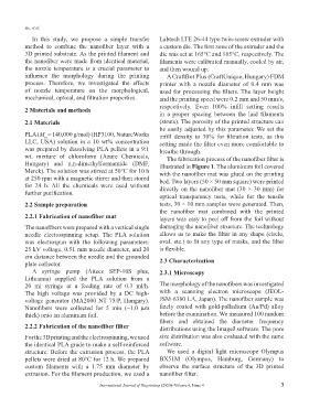
wt. mixture of chloroform (Azure Chemicals, The fabrication process of the nanofiber filter is
Hungary) and n,n-dimethylformamide (DMF, illustrated in Figure 1. The aluminum foil covered
Merck). The solution was stirred at 50°C for 10 h with the nanofiber mat was glued on the printing
at 250 rpm with a magnetic stirrer and then stored bed. Two layers (50 × 50 mm square) were printed
for 24 h. All the chemicals were used without directly on the nanofiber mat (30 × 30 mm) for
further purification.
optical transparency tests, while for the tensile
2.2 Sample preparation tests, 30 × 10 mm samples were generated. Then,
the nanofiber mat combined with the printed
2.2.1 Fabrication of nanofiber mat layers was easy to peel off from the foil without
The nanofibers were prepared with a vertical single damaging the nanofiber structure. The technology
needle electrospinning setup. The PLA solution allows us to make the filter in any shape (circle,
was electrospun with the following parameters: oval, etc.) to fit any type of masks, and the filter
25 kV voltage, 0.51 mm nozzle diameter, and 20 is flexible.
cm distance between the needle and the grounded
plate collector. 2.3 Characterization
A syringe pump (Aitecs SEP-10S plus, 2.3.1 Microscopy
Lithuania) supplied the PLA solution from a
20 ml syringe at a feeding rate of 0.3 ml/h. The morphology of the nanofibers was investigated
The high voltage was provided by a DC high- with a scanning electron microscope (JEOL-
voltage generator (MA2000 NT 75/P, Hungary). JSM-6380 LA, Japan). The nanofiber sample was
Nanofibers were collected for 5 min (~1.0 μm finely coated with gold-palladium (Au/Pd) alloy
thick) onto an aluminum foil. before the examination. We measured 100 random
fibers and obtained the diameter frequency
2.2.2 Fabrication of the nanofiber filter distributions using the ImageJ software. The pore
For the 3D printing and the electrospinning, we used size distribution was also evaluated with the same
the identical PLA grade to make a self-reinforced software.
structure. Before the extrusion process, the PLA We used a digital light microscope Olympus
pellets were dried at 80°C for 12 h. We prepared BX51M (Olympus, Hamburg, Germany) to
custom filaments with a 1.75 mm diameter by observe the surface structure of the 3D printed
extrusion. For the filament production, we used a nanofiber filter.
International Journal of Bioprinting (2020)–Volume 6, Issue 4 3