
Page 125 - IJB-10-6
P. 125
International Journal of Bioprinting Fluid mechanics of extrusion bioprinting
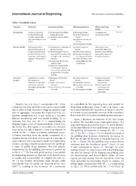
Table 1. Printability criteria
Criterion Definition Assessment method Affecting parameters Effect on printing Ref.
results
Extrudability Ability of a bioink to (i) Visual inspection of fiber (i) Printing pressure; Continuity and 38,40,41,42,43
be extruded through issuing the nozzle; (ii) surface tension of smoothness of fiber
a nozzle continuously (ii) analysis based on Weber bioink;
and controllably to form number (iii) apparent viscosity of
a fiber bioink;
(iv) loss tangent of bioink
Filament fidelity Deformation of the (i) Analyzing the uniformity of (i) Surface tension of Altering the cross- 44, 45–49
deposited filament as it the cross-section; bioink; sectional profile of the
bridges over previously (ii) determining the ratio of (ii) yield stress of bioink; filament across different
printed filaments in the the printed filament’s width (iii) storage modulus and layers and locations of
lower layer, with limited or height to the theoretical loss tangent of bioink; the printed scaffold
sagging or filling of the diameter; (iv) elastic modulus of the
pores (iii) examining the pore size printed filament after
within a layer; crosslinking
(iv) filament collapse test by
extruding the filament
over a series of pillars with
progressively increasing
spacing
Structural Capability of a printed (i) Thickness of individual (i) Surface tension of (i) Fusion of printed 36,38, 50,44,51
integrity 3D construct to layers; bioink; filaments at their
maintain its shape and (ii) height of the whole (ii) wettability of bioink; intersections;
dimensions similar to construct; (iii) viscosity recovery rate (ii) deformation and
the original design after (iii) size of pores in the vertical of bioink; overhang on the
printing direction (iv) loss tangent of bioink filaments of the
lower layer
Notably, Case A in Figure 1 corresponds to We = 0; the jet controllable by the dispensing force and suitable for
bioink does not flow out of the nozzle and is unextrudable bioprinting applications. Cases C and D in Figure 1 are
due to either its high viscosity or clogging caused by large more associated with the viscoelastic or dynamic behavior
cells or aggregates. Increasing the dispensing force can of a bioink, as experimentally observed on the viscoelastic
improve extrudability, but it may result in a fractured fluid stream (0.01 wt% polyacrylamide aqueous solution). 52
filament morphology and even nozzle breakage. At an Figure 2 illustrates the behavior of the fluid stream
extremely low flow rate, We << 1, characterizing the at various We, recorded using a high-speed camera. The
dripping regime, drops of liquid periodically detach from sequential images presented in Figure 2A and B illustrate
the nozzle. This flow regime is not suitable for extrusion the dynamic behavior of the liquid stream at 5 ms intervals.
bioprinting as it fails to deposit a continuous filament of The gobbling phenomenon is obvious for We < 1 and
bioink. At We < 1, there is a limited continuous stream We ~1. For We < 1 (Figure 2A), the detachment point of
of bioink extruding from the nozzle, terminated by a the gobbling drop fluctuates periodically. Increasing the
terminal droplet detaching from its end in a periodic or flow rate changes the dynamic of the gobbling drop, and
chaotic manner. For a viscoelastic liquid, the terminal drop at We ~1 (Figure 2B), the gobbling drop remains almost
reaches a size larger than the nozzle diameter by “gobbling” stationary near the detachment point. Figure 2A and
55
a chain of smaller drops upstream. This flow pattern, B both correspond to Figure 1C. Although the small
characterized by the gobbling phenomenon, persists up spacing between the dispensing nozzle and printing stage
55
to We of ~1. The flow with gobbling drop is not suitable can alter the dynamic of the dripping and gobbling flow,
for bioprinting because the diameter of the liquid stream the discontinuous and uncontrollable nature of these
is variable and uncontrollable. At a higher flow rate, i.e., regimes prevents smooth filament deposition, rendering
We >1, the droplets’ detachment point abruptly shifts them unsuitable for bioprinting. Figure 2C displays the
downstream from the nozzle exit (typically farther than jetting regime characterized with We < 1, corresponding
20Ri 52,53 ), resulting in the formation of a continuous to Figure 1D. While jet flow with We > 1 will break up
Volume 10 Issue 6 (2024) 117 doi: 10.36922/ijb.3973