
Page 129 - IJB-10-6
P. 129
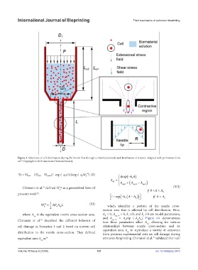
International Journal of Bioprinting Fluid mechanics of extrusion bioprinting
Figure 3. Schematic of cell deformation during the bioink flow through a chamfered nozzle and distribution of stresses. Adapted with permission from
63
ref. Copyright © 2018 American Chemical Society.
eq
b e)]}exp (–a pW p ) (X)
D t = D max – {D max – D e,max[1–exp (–a eτ e Aexp − ( k A) if 0 < A < A
A = A ( 1 0
k AA− ))
eq
exp
A eq 0 , + eq ∞, − A ) 1 − ( − ( 0 if A > A 0
2
eq 0 ,
Chirianni et al. defined W as a generalized form of (XII)
eq
74
p Aexp − ( k A) if 0 < A < A
pressure work : A = A ( 1 0
74
k AA− ))
eq
exp
A eq 0, + eq ∞, − A ) 1 − ( − ( 0 if A > A 0
2
eq 0,
W = 1 ∆ P AL (XI) which identifies a portion of the nozzle cross-
eq
eq
n
p
2
section area that is affected by cell distribution. Here,
where A is the equivalent nozzle cross-section area. A > 0, A e q, ∞ > 0, k ≥ 0, and k ≥ 0 are model parameters,
2
1
0
eq
Chirianni et al. described the different behavior of and A e q, 0 = A exp (–k A ). Figure 4A demonstrates
2
0
0
74
how these parameters affect A , allowing for various
eq
cell damage in Scenarios 1 and 2 based on uneven cell relationships between nozzle cross-section and its
equivalent area A to reproduce a variety of outcomes
distribution in the nozzle cross-section. They defined eq
from previous experimental tests on cell damage during
74
equivalent area A as 74 extrusion bioprinting. Chirianni et al. validated their cell
eq
Volume 10 Issue 6 (2024) 121 doi: 10.36922/ijb.3973