
Page 143 - IJB-10-6
P. 143
International Journal of Bioprinting Fluid mechanics of extrusion bioprinting
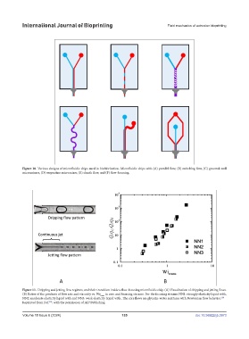
Figure 10. Various designs of microfluidic chips used in biofabrication. Microfluidic chips with (A) parallel flow, (B) switching flow, (C) grooved-wall
Figure 10. Various designs of microfluidic chips used in biofabrication. Microfluidic chips with
micromixers, (D) serpentine micromixer, (E) sheath flow, and (F) flow-focusing.
(A) parallel flow, (B) switching flow, (C) grooved-wall micromixers, (D) serpentine
micromixer, (E) sheath flow, and (F) flow-focusing.
75
Figure 11. Dripping and jetting flow regimes, and their transition inside a flow-focusing microfluidic chip. (A) Visualization of dripping and jetting flows.
(B) Ratios of the products of flow rate and viscosity vs. We trans in core and focusing streams. For the focusing streams NN1: strongly elasticity liquid with,
NN2: moderate elasticity liquid with and NN3: weak elasticity liquid with . The core flows are glycerin-water mixtures with Newtonian flow behavior. 158
Reprinted from Ref. , with the permission of AIP Publishing.
158
Volume 10 Issue 6 (2024) 135 doi: 10.36922/ijb.3973