
Page 147 - IJB-10-6
P. 147
International Journal of Bioprinting Fluid mechanics of extrusion bioprinting
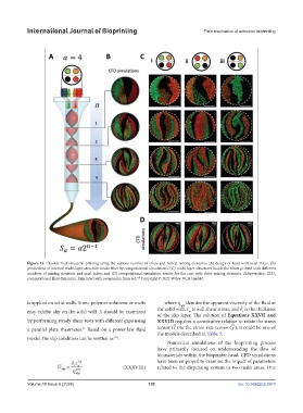
Figure 13. Chaotic multi-material printing using the various number of inlets and helical mixing elements; (A) design of head with axial inlets, (B)
predictions of internal multi-layer structure inside fiber by computational simulations, (C) multi-layer structures inside the fibers printed with different
numbers of mixing elements and axial inlets, and (D) computational simulation results for the case with three mixing elements. Abbreviation: CFD,
computational fluid dynamics. Reprinted with permission from ref. Copyright © 2023 Wiley‐VCH GmbH.
169
is applied on solid walls. Some polymer solutions or melts where η denotes the apparent viscosity of the fluid at
app
the solid wall, τ is wall shear stress, and δ is the thickness
may exhibit slip on the solid wall. It should be examined w t
of the slip layer. The solution of Equations XXVII and
by performing steady shear tests with different gaps using XXVIII requires a constitutive relation to relate the stress
=
=
a parallel plate rheometer. Based on a power-law fluid tensor (τ ) to the strain rate tensor (γ ); it could be one of
78
the models described in Table 3.
model, the slip condition can be written as :
176
Numerical simulations of the bioprinting process
have primarily focused on understanding the flow of
biomaterials within the bioprinter head. CFD simulations
δτ 1/ n have been employed to examine the impact of parameters
U slip = tw n (XXXVIII) related to the dispensing system in two main areas. One
1/
η app
Volume 10 Issue 6 (2024) 139 doi: 10.36922/ijb.3973