
Page 149 - IJB-10-6
P. 149
International Journal of Bioprinting Fluid mechanics of extrusion bioprinting
modeled the alginate-based bioink as a power-law fluid bioink reduces the flow rate within the printing head by
and the crosslinker (calcium chloride) as a Newtonian hampering the flow inside the nozzle. To date, no CFD
196
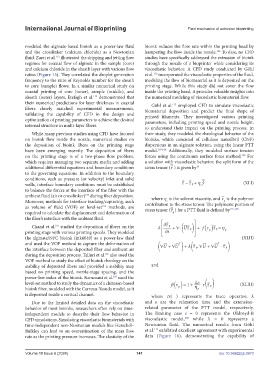
fluid. Zarei et al. illustrated the dripping and jetting flow studies have specifically addressed the extrusion of bioink
113
regimes for coaxial flow of alginate in the sample (core) through the nozzle of a bioprinter while considering its
and calcium chloride in the sheath layer with various flow viscoelastic behavior. A CFD study conducted by Göhl
ratios (Figure 15). They correlated the droplet generation et al. incorporated the viscoelastic properties of the fluid,
112
frequency to the ratio of Reynolds number for the sheath modeling the flow of biomaterial as it is deposited on the
to core (sample) flows. In a similar numerical study on printing stage. While this study did not cover the flow
coaxial printing of core (inner), sample (middle), and inside the printing head, it provides valuable insights into
sheath (outer) layers, Etefagh et al. demonstrated that the numerical modeling of viscoelastic biomaterial flow.
114
their numerical predictions for layer thickness in coaxial Göhl et al. employed CFD to simulate viscoelastic
112
fibers closely matched experimental measurements, biomaterial deposition and predict the final shape of
validating the capability of CFD in the design and printed filaments. They investigated various printing
optimization of printing parameters to achieve the desired parameters, including printing speed and nozzle height,
internal structure in multi-layer fibers. to understand their impact on the printing process. In
While many previous studies using CFD have focused their study, they modeled the rheological behavior of the
on bioink flow inside the nozzle, numerical studies on bioinks, which consisted of cellulose nanofibril (CNF)
the deposition of bioink fibers on the printing stage dispersions in an alginate solution, using the linear PTT
have been emerging recently. The deposition of fibers model. 197,198 Additionally, they modeled surface tension
on the printing stage is of a two-phase flow problem, forces using the continuum surface force method. For
199
which requires managing two separate media and adding a solution with viscoelastic behavior, the split form of the
=
additional differential equations and boundary conditions stress tensor (τ ) is given by
78
to the governing equations. In addition to the boundary
conditions, such as pressure (or velocity) inlet and solid i
walls, interface boundary conditions must be established τ = τ + ηγ (XLI)
p
s
to balance the forces at the interface of the fiber with the
=
194
ambient fluid (air or crosslinker) during fiber deposition. where η is the solvent viscosity, and τ is the polymer
Moreover, methods for interface tracking/capturing, such contribution to the stress tensor. The polymeric portion of
s
p
194
=
as volume of fluid (VOF) or level-set methods, are stress tensor (τ ) for a PTT fluid is defined by 197,198
required to calculate the displacement and deformation of p
the fiber’s interface with the ambient fluid.
( )
(
τ τ )
T
Chand et al. studied the deposition of fibers on the λ τ ∂ p +∇⋅ U τ p + ( p p = η ∇ +∇U U T ) ( pi U U ⋅τ p )
187
λτ ∇ +∇U
+
f
printing stage with various printing speeds. They modeled ∂t p
the alginate/NFC bioink (ink6040) as a power-law fluid (XLII)
( )
(
τ ∂
and used the VOF method to capture the deformation of f τ τ ) = η ∇ +∇U U T ) ( U U ⋅τ )
T
λ
p
λτ ∇ +∇U
+
+∇⋅ U
τ p
the interface between the deposited fiber and ambient air p p pi p
+ ( p
∂t
during the deposition process. Talluri et al. also used the
195
VOF method to study the effect of bioink rheology on the
stability of deposited fibers and provided a stability map and
based on printing speed, nozzle-stage spacing, and the
power-law index of the bioink. Ramezani et al. used the
195
level-set method to study the dynamics of a chitosan-based τ ( ) =+1 λε r τ ( p) (XLIII)
bioink fiber, modeled with the Carreau-Yasuda model, as it p η p
is deposited inside a vertical channel. where tr( ) represents the trace operator; λ
Due to the limited detailed data on the viscoelastic and ε are the relaxation time and the extension-
behavior of most bioinks, researchers often rely on time- related parameter of the PTT model, respectively.
independent models to describe their flow behavior in The limiting case ε = 0 represents the Oldroyd-B
200
CFD simulations. Simulating viscoelastic biomaterials with viscoelastic model, while λ = 0 represents a
time-independent non-Newtonian models like Herschel– Newtonian fluid. The numerical results from Göhl
112
Bulkley can lead to an overestimation of the mass flow et al. exhibtied excellent agreement with experimental
rate as the printing pressure increases. The elasticity of the data (Figure 16), demonstrating the capability of
Volume 10 Issue 6 (2024) 141 doi: 10.36922/ijb.3973