
Page 146 - IJB-10-6
P. 146
International Journal of Bioprinting Fluid mechanics of extrusion bioprinting
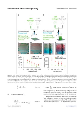
Figure 12. Multi-material bioprinting of 2D and 3D structures with a stiffness gradient, controlled by mixing two carboxylated agarose hydrogels with
different stiffness. (A) printing of 2D structures with controlled stiffness gradient (B) printing of 3D structures with controlled stiffness gradient, (C) 2D
structure with medium-soft stiffness gradient, (D) 2D structure with stiff-soft stiffness gradient, (E) 3D structure with medium-soft stiffness gradient,
(F) 3D structure with stiff-soft stiffness gradient. (G) Variation of elastic modulus with position in 2D printed structures, (H) variation of elastic modulus
164
with position in 3D printed structures. Soft, medium, and stiff carboxylated agarose hydrogels are colored in blue, green, and red respectively. Scale
bars: 10 mm for C, D, and 1 mm for E, F. Abbreviation: E modulus, elastic modulus. Adapted from ref. Copyright © 2021 American Chemical Society.
164
D ρ ( )
∂ρ D U ∂ρ
=−∇+ ∇⋅
+∇⋅ p
τ +
= 0 ρ
Dt
∂t +∇⋅ ρU = 0 (XXXVI) where Dt is the material derivative; ρU and g are
∂t
vectors representing the fluid velocity and gravitational
acceleration, respectively; p and ρ denote the pressure and
(ii) Momentum transport : density of the fluid, respectively; and τ is the stress tensor.
70
The boundary condition at the inlet of a dispensing
head is the given pressure or inlet velocity for pneumatic
D ρ ( ) or piston-driven systems, respectively. The nozzle outlet is
U
set to ambient pressure, and a no-slip boundary condition
p
=−∇+ ∇⋅ τ + ρ g (XXXVII)
Dt
Volume 10 Issue 6 (2024) 138 doi: 10.36922/ijb.3973