
Page 219 - IJB-10-6
P. 219
International Journal of Bioprinting 3DP Ta buttress in DDH shelf acetabuloplasty
computed tomography (CT) images were converted into (i) The bone healing surface of the tantalum buttress
digital image correlation method (DICM) format using matched the anatomical morphology of the
INFINITT software (Infinitt, China). Patient CT data were outer table of the pelvis and the outer rim of the
imported into Mimics Research 19.0 software (Materialise, acetabulum with high precision. The curvature of the
Belgium). Threshold-based and dynamic segmentations bottom surface (capsular healing surface) paralleled
were conducted to extract masks for the pelvis, sacrum, and the spherical surface of the femoral head, achieving
proximal ends of both femurs, converting them into 3D concentric support.
models. These models were then exported in STL format
and reverse-engineered using Geomagic Studio software (ii) After implantation, the LCE angle should be within
(Geomagic, United States of America [USA]) to generate the range of 30–35° and the anterior center-edge
STP format data. Deviation analysis was performed on the (ACE) angle within 25–30°.
STP data before and after reverse engineering to provide (iii) The tantalum buttress must completely cover the
foundational digital models and design references for the lateral superior defect area of DDH, including the
structural design of components for patients with DDH. area from the anterior 3 o’clock position to the
posterior 9 o’clock, ensuring that the non-coverage
2.2.2. Design of the 3D-printed porous area of the femoral head in anteroposterior view was
tantalum buttress approximately 1/5 of the diameter of the femoral head.
The STP file was imported into UG software (Unigraphics NX,
USA), establishing a coordinate system in a normal standing (iv) Three screw holes with a diameter of 5.0 mm were
position, and adjusting the 3D spatial position of the pelvis to designed on the tantalum buttress, capable of
ensure it was fully placed in a neutral position. The design of accommodating three screws for double-row fixation
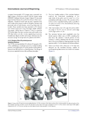
the porous tantalum buttress followed these principles: (Figure 1).
Figure 1. Design of the 3D-printed porous tantalum buttress. (A) The curvature of the bottom surface of the buttress parallels the spherical surface of the
femoral head, achieving concentric support. (B) The lateral center-edge (LCE) angle is designed to be 35°. (C) The anterior center-edge (ACE) angle is
designed to be 30°. (D) The non-coverage area of the femoral head is approximately 1/5 of its diameter.
Volume 10 Issue 6 (2024) 211 doi: 10.36922/ijb.4074