
Page 130 - IJB-7-1
P. 130
Actualizing Hybrid Pressure and Silicone Therapies with 3D Printing and Scanning
A F G
B E H
C D I
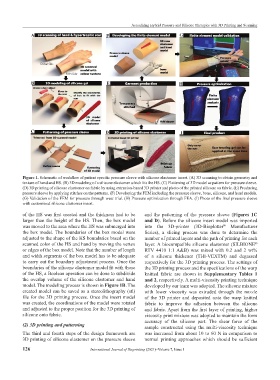
Figure 1. Schematic of workflow of patient specific pressure sleeve with silicone elastomer insert. (A) 3D scanning to obtain geometry and
texture of hand and HS. (B) 3D modeling of a silicone elastomer which fits the HS. (C) Flattening of 3D model as pattern for pressure sleeve.
(D) 3D printing of silicone elastomer on fabric by using extrusion-based 3D printer and photo of the printed silicone on fabric. (E) Producing
pressure sleeve by applying stitches on the patterns. (F) Developing the FEM including the pressure sleeve, bone, silicone, and hand models.
(G) Validation of the FEM for pressure through wear trial. (H) Pressure optimization through FEA. (I) Photo of the final pressure sleeve
with customized silicone elastomer insert.
of the HS was first created and the thickness had to be and the patterning of the pressure sleeve (Figures 1C
larger than the height of the HS. Then, the box model and D). Before the silicone insert model was imported
was moved to the area where the HS was submerged into into the 3D-printer (3D-Bioplotter Manufacturer
®
the box model. The boundaries of the box model were Series), a slicing process was done to determine the
adjusted to the shape of the HS boundaries based on the number of printed layers and the path of printing for each
scanned color of the HS and hand by moving the vertex layer. A biocompatible silicone elastomer (SILBIONE
®
or edges of the box model. Note that the number of length RTV 4410 1:1 A&B) was mixed with 0.2 and 2 wt%
and width segments of the box model has to be adequate of a silicone thickener (THI-VEXTM) and degassed
to carry out the boundary adjustment process. Once the respectively for the 3D printing process. The settings of
boundaries of the silicone elastomer model fit with those the 3D printing process and the specifications of the warp
of the HS, a Boolean operation can be done to subdivide knitted fabric are shown in Supplementary Tables 1
the overlap volume of the silicone elastomer and hand and 2, respectively. A multi-viscosity printing technique
model. The modeling process is shown in Figure 1B. The developed by our team was adopted. The silicone mixture
created model can be saved as a stereolithography (stl) with lower viscosity was extruded through the nozzle
file for the 3D printing process. Once the insert model of the 3D printer and deposited onto the warp knitted
was created, the coordinations of the model were rotated fabric to improve the adhesion between the silicone
and adjusted to the proper position for the 3D printing of and fabric. Apart from the first layer of printing, higher
silicone onto fabric. viscosity print mixture was adopted to maintain the form
accuracy of the silicone part. The shear force of the
(2) 3D printing and patterning sample constructed using the multi-viscosity technique
The third and fourth steps of the design framework are was increased from about 10 to 60 N in comparison to
3D printing of silicone elastomer on the pressure sleeve normal printing approaches which should be sufficient
126 International Journal of Bioprinting (2021)–Volume 7, Issue 1