
Page 82 - IJB-8-1
P. 82
Geometric Accuracy of 3D Printed Dental Implant
perform a segmentation of the same tooth three times in previous sections was carried out using a SLM 280
and the average of the three parameters was used as the HL machine from SLM Solutions AG, Germany. The
standard. machine was equipped with a Gaussian beam fiber laser
3D Shape Convince software was used to evaluate with maximum power of 400 W and a focal diameter of
the accuracy of the segmentation and printing process. 80 μm. All processing occurred in an argon environment
The extracted tooth and 3D printed dental implant with <0.05% oxygen to prevent oxidation and degradation
were scanned using a micro-CT and converted into an of the material during the process. The material used was
STL format. This was compared against the original commercially pure titanium powder (Grade 2 ASTM
STL file that was used to print the dental implant. The B348, LPW Technology Ltd, United Kingdom), The
overall accuracy of both processes was evaluated by powder was spherical in shape and had particle size with
aligning the two STL models using the software’s best fit average of 43.5 μm. The processing parameters used
algorithm, then comparing the percentage of the surface are summarised in Table 1. A stripe scanning strategy
area that deviates within a +0.1 mm tolerance limit. For was used with stripe width 10.0 mm. A schematic of the
the segmentation process, the original segmented STL scanning pattern is shown in Figure 2.
was compared against the actual tooth model. For the To ensure that the geometry of the fabrication
L-PBF process, the printed tooth was compared against samples was not due to the L-PBF process, preliminary
the original STL. The overall accuracy of the entire studies were carried out to obtain the correction factor for
fabrication process was evaluated by comparing the the L-PBF process. In these preliminary studies, cones
printed tooth to the actual tooth (n = 8 as only 8 teeth with dimensions 4 mm × 5 mm × 8 mm were fabricated.
were extracted from the tooth socket). The schematic of the samples fabricated is shown in
Figure 3. The results are tabulated in Table 2. The
2.4. L-PBF fabrication correction factor with least deviations (0.996) is applied
for the fabrication of the specimens.
In this study, the fabrication of actual samples using
STL files obtained from the segmentation described 3. Results
The 3D printed dental implant was fabricated based
A B on the STL files obtained from the segmentation of the
monkey incisor from its maxilla, then compared against
the extracted tooth (Figure 4). The 3D printed dental
implant measured approximately 1 cm along its entire
length.
Overall, our findings showed that the fabrication
process produced a 3D printed dental implant that
achieved 68.70% ± 5.63 (n = 8) accuracy compared to the
C D actual tooth. This implant fabrication was based on the
3D segmented tooth model that had a relatively similar
level of accuracy of 66.91% ± 10.51 (n = 14) during the
segmentation process (Table 3 and Table S1). It was
noted that the main regions of inaccuracies were at the
tooth apex (blue colored zones) (Figure 5).
The L-PBF process had a 90.59% ± 4.75 accuracy
(n = 8) (Table 3). The deviation between the RAI and the
Table 1. Process parameters used in L-PBF for fabrication of
samples
Process parameters
Laser power (W) 275
Laser scan speed (mm/s) 1100
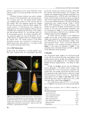
Figure 1. Segmentation of dental implant from a tooth model of Layer thickness (μm) 30
the maxilla. (A) Segmentation of tooth along the cementoenamel Hatch spacing (mm) 0.120
junction (CEJ) based on the computed tomography scan (yellow Fill Contour Offset (mm) 0.06
outlined area). (B) Outline of CEJ on tooth model. (C) Plane of
segmentation (represented by green line) 1.0 mm above the CEJ. Boarders (mm) 0.09
(D) Model of segmented dental implant. Remelting No
68 International Journal of Bioprinting (2022)–Volume 8, Issue 1