
Page 11 - IJB-8-3
P. 11
Liu, et al.
for scaffold fabrication were fixed at the temperature of onto the sample with a current of 30 mA for 30 s to
25 ± 1°C and relative humidity of 65 ± 10%. form a conductive layer. Subsequently, the samples were
analyzed with the following settings: Beam energy at
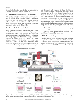
2.3. Post-processing of printed RPE scaffolds 10 kV, dwell time of 6 μs, a spot size of 4.0, and collection
The printed scaffolds on silicon wafer were transferred with a large field detector. Morphology information was
into a vacuum drying chamber to discard the excess obtained at 1000×, whereas the side-mounted samples
AcOH for 2 h. The scaffolds were detached from the were used for cross-sectional imaging and thickness
silicon wafer, cut into round shapes with a diameter of measurements at 2000×. PET membranes were processed
11 mm with a round shape cutter, and then attached to the and evaluated using the same parameters and procedures,
empty cell culture inserts (Figure 1B). except the pore sizes. The porosity (Φ) was calculated by
ρ
2.4. Morphological characterization Φ= 1− s (2.1)
ρ 0
Fiber diameters, pore sizes, and fiber alignment of the
scaffolds were examined and measured using an optical Where, ρ and ρ are the apparent densities of the
s
0
microscope (EZ4 HD, Leica, Germany). The results were scaffolds and biomaterials, respectively.
expressed as mean ± standard deviations. Furthermore, 2.5. Mechanical testing
the morphology was characterized using a scanning
electron microscope (SEM, FEI Quanta 250, Thermo The initial part of the stress-strain curve was obtained
Fisher Scientific, USA). Samples were sectioned into using the Dynamic Mechanical Analysis (DMA, Q800, TA
the size of 5 mm × 5 mm and were mounted on a round Instruments, USA) instrument at room temperature. The
metal stud using conductive copper tape for surface or ultimate stress and strain were examined using a universal
cross-sectional imaging. Sputter coating was applied testing machine (HDB609B-S, Haida International
A
B
C
Figure 1. Process of building RPE models using EHDJ-printed PCL scaffolds. (A) Fabricating ultrathin monolayer PCL scaffolds through
EHDJ printing. (B) Post-processing of the printed scaffolds. (C) Seeding and culturing of RPE cells.
3 International Journal of Bioprinting (2022)–Volume 8, Issue 3