
Page 162 - IJB-8-3
P. 162
3DP Modularized Finger PIPJ Arthroplasty
into the natural articular surface using the iterative closest and greater than the joint surface over two levels were
points (ICP) algorithm provided in the Mimics software. excluded, leaving the modularized PIP joint implant the
The calculation formula is shown in : modularized with the same size and the joint surface
[9]
(
E R, ) T = ∑ n = i 1 ( ( * +R pi T ) − qi )2 greater than one level of the stem. From the anatomical
and clinical consideration, the medullary cavity could be
where pi is the point cloud coordinates for the occasional smaller due to thick metaphyseal of diaphyseal
alignment model P, qi is the point cloud coordinates cortical bone. However, mismatch with large medullary
for the target alignment model Q, n is the number cavity with smaller articulation was seldom observed,
of reference point clouds (n = 1000), R is the rotation which may affect the range of motion of joint. Under such
matrix, and T is the translation matrix. Each iteration is conditions there were a total of nine sets of specifications
intended to calculate the distance between the point cloud (Table 1).
pi coordinates for the alignment model and the point For the subsequent functional biomechanical
cloud qi coordinates for the target alignment model after test requirements, it was necessary to determine the
matrix transformation. The iteration was stopped when combination of nine PIP joint implant specification
the difference between the front and rear transformation sets with the weakest structure after the PIP joint was
matrices is less than the set threshold value. This iteration implanted with the phalanx. When the medullary cavity
process enabled phalanges of different sizes to align with ratio to the entire phalanx cross-sectional areas was
the large shared volume. Natural articular surfaces in the largest, that is, the one with the smallest cortex bone
clinical representatives were obtained by averaging the thickness was defined as the weakest state structure.
coordinates from the 48 aligned point clouds of phalanx A structural weakness combination from the nine PIP
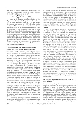
articular surfaces (Figure 2A). joint implants can be found using the following three
steps: (i) the phalanges with the largest size, medium
2.2. Modularized PIP joint implant system size (averaged size) and the smallest size among the 48
design and worst structure case definition phalanges were screened; (ii) corresponding medullary
The components for resurfacing the PIP joint implant cavity ratio to the cross-sectional area at the phalanx stem
include three parts, bi-condylar surface with elliptical- top and bottom sides of the previous largest and medium
cone stem of proximal phalanx, the bi-concave articular sizes were obtained and these sizes were recorded to
surface of middle phalanx, and the elliptical-cone stem find the phalange with maximum ratio, that is, the PIP
of middle phalanx. The bi-concave articular surface was joint with the thinnest cortex bone case; and (iii) the
designed to connect with the elliptical-cone stem using a combination of nine groups of PIP joint implants that can
be put into the case of the thinnest cortex bone with the
hook mechanism (Figure 2B and C). largest stem size was checked. Furthermore, a larger force
The averaged stem lengths (12 mm for proximal
stem and 7.5 mm for middle stem), major and minor axis state can be generated when the articular surface level was
larger than the corresponding stem level combination.
of the elliptical-cone stem at metaphyseal and diaphyseal
for proximal and middle phalanxes were calculated from Therefore, the structural weakness combination from
the 48 sets of phalanx CT image data and noted as the the nine PIP joint implants can be found and defined as
standard size specification (Figure 2B and C). Since the worst structure case. This combination was used for
the size of 20% above/below the standard PIP joint functional mechanical test to observe the biomechanical
implant size was about the average dimension plus/minus performance of modularized pairing under different
1.3 standard deviation, covering about 80% of the 48 specifications.
phalanges’ size. The size was set at 20% above and below 2.3. 3D printing manufacture of the worst PIP
the averaged standard size as the maximum and minimum joint implant
sizes, respectively. An intermediate size of 10% was
inserted to cover the entire PIP joint implant detailed The proximal phalangeal stem and articular surface
size range. Finally, a total of five sizes for the PIP joint components as well as the middle phalangeal stem were
implant, consisting of 20%, 10%, standard size, −10% fabricated by metal 3D printer (AM400, Renishaw,
and −20%, were considered (Table 1). There were five Gloucestershire, UK) with titanium alloy powder (about
specifications for both the articular surfaces and the cone 30 μm), which had been proved with good biocompatibility
stems for proximal and middle phalanxes, which in free and was also used widely in clinical practice. Our 3D
combination would make up 25 sets of modularized printer laboratory was approved by ISO13485 quality
specifications. management system (Certificate Number: 1760.190828)
Considering the more plausible combination of to ensure that implants manufactured by 3D printing can
the stem and articular surface of anatomical proportion, provide a practical foundation to meet the regulations,
the modularized PIP joint implant with the stem smaller such as printing material with biocompatibility in the
154 International Journal of Bioprinting (2022)–Volume 8, Issue 3