
Page 165 - IJB-8-3
P. 165
Hunag, et al.
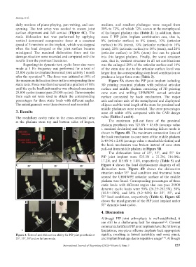
daily motions of piano-playing, pen-writing, and can- medium, and smallest phalanges were ranged from
opening. The test setup was needed to ensure joint 30% to 72%, of which 72% occurs at the metaphyseal
surface alignment and full contact (Figure 4C). The of the largest phalanx size (Table 2). In addition, there
static dislocation test was performed by applying were 5 PIP joint implant combination sets, that is,
vertical downward compressive force at a constant 0% (articular surface) to 0% (stem), 10% (articular
speed of 5 mm/min on the implant, which was stopped surface) to 0% (stem), 10% (articular surface) to 10%
when the load dropped or the joint surface became (stem), 20% (articular surface) to 10% (stem), and 20%
misaligned. The maximal dislocation force and the (articular surface) to 20% (stem) that can be placed
damage situation were recorded and compared with the into this largest phalanx. Finally, the worst structure
results from the previous literatures. case, that is, weakest structure in all set combinations
Regarding the dynamic test, cyclic force sine wave was the enlarged 20% of the articular surface and 10%
mode at 1 Hz frequency was performed for a total of of the stem size due to the articular surface level was
25,000 cycles to simulate the normal joint activity 1 month larger than the corresponding stem level combination to
after the operation . The force was initiated at 50% of produce a larger force state (Table 2).
[13]
the maximum dislocation force in the corresponding three Figure 5A shows the PIP joint implant including
static tests. Force was then increased at a gradient of 10% 3D printing proximal phalanx with polished articular
until the cyclic load limit number was obtained maximum surface and middle phalanx consisting of 3D printing
25,000 cycles (cannot pass 25,000 cycles). Three samples cone stem and milling UHMWPE curved articular
from each set were used to obtain the corresponding surface connected by hook mechanism. The major
percentages for three static loads with different angles. axis and minor axis of the metaphyseal and diaphyseal
The misalignments were then observed and recorded. ellipses and the total length of the stem for proximal and
middle phalanxes were recorded. The error percentages
3. Results were all within ±5% compared with the CAD design
The medullary cavity ratio to the cross-sectional area value (Tables 3 and 4).
at the phalanx stem top and bottom sides of largest, The maximum pull-out force of the proximal
phalanx prosthesis was 727.8N ± 45.6N (average value
A B ± standard deviation) and the loosening failure mode is
shown in Figure 4B. The maximum connection force of
the hook mechanism to cone stem of the middle phalanx
is 49.9N ± 2.0N (average value ± standard deviation) and
the hook mechanism was broken instead of cone stem
pull-out from middle phalanx in Figure 3D.
The dislocation force of 25°, 35°, and 55° for
PIP joint implant were 525.3N ± 21.2N, 316.0N±
17.2N, and 115.0N ± 1.8N, respectively (Table 5) and
C Figure 6 shows the load displacement diagram of all
dislocation tests. Figure 4D shows the dislocation
situation under 35° load condition and fractured bone
around the UHMWPE articular surface of the middle
phalanx was found. Corresponding percentages of three
static loads with different angles that can pass 25000
dynamic cyclic loads were 50% (26.25~262.5N), 50%
(15.8~158N), and 80% (9.2~92N) for 25°, 35°, and
55° load conditions, respectively (Table 6). Figure 6E
D E shows the misalignment of the PIP joint implant under
55° dynamic load cycles.
4. Discussion
Although PIP joint arthroplasty is well-established, it
can still be a challenging task for surgeons [1,2] . Current
commercial artificial PIP joint implants have the following
limitations; one-piece silicone implants lack appropriate
Figure 4. Tests of anti-dislocation ability for PIP joint prosthesis at rigidity, resulting in lateral instability and weak pinch,
25°, 35°, 55°and on failure mode. and implant breakage due to repetitive usage [1-4] . Although
International Journal of Bioprinting (2022)–Volume 8, Issue 3 157