
Page 164 - IJB-8-3
P. 164
3DP Modularized Finger PIPJ Arthroplasty
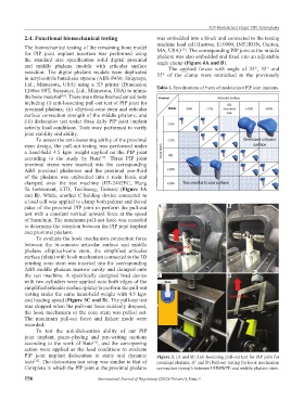
2.4. Functional biomechanical testing was embedded into a block and connected to the testing
The biomechanical testing of the remaining bone model machine load cell (Instron, E10000, INSTRON, Canton,
MA, USA) . The corresponding PIP joint at the middle
[13]
for PIP joint implant insertion was performed using phalanx was also embedded and fixed into an adjustable
the standard size specification solid digital proximal angle clamp (Figure 4A and B).
and middle phalanx models with articular surface The applied forces with angle of 25°, 35° and
resection. The digital phalanx models were duplicated 55° of the clamp were mimicked to the previously
in acrylonitrile butadiene styrene (ABS-P430; Strayasys,
Ltd., Minnesota, USA) using a 3D printer (Dimension Table 1. Specifications of 9 sets of modularized PIP joint implants.
1200es SST, Strayasys, Ltd., Minnesota, USA) to mimic
the bone material . There were three biomechanical tests
[10]
including (i) anti-loosening pull-out test of PIP joint for
proximal phalanx; (ii) elliptical-cone stem and articular
surface connection strength of the middle phalanx; and
(iii) dislocation test under three daily PIP joint implant
activity load conditions. Tests were performed to verify
joint stability and ability.
To assess the anti-loosening ability of the proximal
stem design, the pull-out testing was performed under
a hand-held 4.5 kgw weight applied on the PIP joint
according to the study by Butz . Three PIP joint
[11]
proximal stems were inserted into the corresponding
ABS proximal phalanxes and the proximal one-third
of the phalanx was embedded into a resin block and
clamped onto the test machine (HT-2402EC, Hung
Ta Instrument, LTD, Taichuang, Taiwan) (Figure 3A
and B). While, another C holding device connected to
a load cell was applied to clamp both palmar and dorsal
sides of the proximal PIP joint to perform the pull-out A B
test with a constant vertical upward force at the speed
of 5mm/min. The maximum pull-out force was recorded
to determine the retention between the PIP joint implant
and proximal phalanx.
To evaluate the hook mechanism connection force
between the bi-concave articular surface and middle
phalanx elliptical-cone stem, the simplified articular
surface (plate) with hook mechanism connected to the 3D
printing cone stem was inserted into the corresponding
ABS middle phalanx marrow cavity and clamped onto
the test machine. A specifically designed load device C D
with two cylinders were applied onto both edges of the
simplified articular surface (plate) to perform the pull-out
testing under the same hand-held weight with 4.5 kgw
and loading speed (Figure 3C and D). The pull-out test
was stopped when the pull-out force suddenly dropped,
the hook mechanism or the cone stem was pulled out.
The maximum pull-out force and failure mode were
recorded.
To test the anti-dislocation ability of our PIP
joint implant, piano-playing and pen-writing motions
according to the work of Butz , and the can-opening
[11]
action were applied as the load conditions to evaluate
PIP joint implant dislocation in static and dynamic Figure 3. (A and B) Anti-loosening pull-out test for PIP joint for
tests . The dislocation test setup was similar to that of proximal phalanx; (C and D) Pull-out testing for hook mechanism
[12]
Completo in which the PIP joint at the proximal phalanx connection strength between UHMWPE and middle phalanx stem.
156 International Journal of Bioprinting (2022)–Volume 8, Issue 3