
Page 411 - IJB-9-3
P. 411
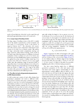
International Journal of Bioprinting                                     Cellular metamaterial flexure joints


                         A                                   B


            Figure 2. Comparing stiffness characteristics of: (A) Conventional flexure joint commonly used in soft robotic fingers; (B) the proposed metamaterial
            flexure joint.

            multi-stiffness behavior of the MFJ can be tuned through   unit cells include the length of the re-entrant struts (w),
            altering the geometrical parameters of the unit cells.  the thickness of the re-entrant struts (δ), the thickness of
                                                               vertical struts (t), the length of the vertical struts (l), and
            4.1.2. Large range of bending motion
                                                               the re-entrant angle (θ). The range of these parameters are
            The large range of bending motion of the MFJ is mainly   constrained with the desired size of the joint, including
            due to the auxetic characteristics of the re-entrant unit   length (L), width (W), and depth (D), and the geometrical
            cells used in its architecture, which is also known as   relation between them to ensure that the joint is realizable
            negative Poisson ratio . The structures with auxetic   with the tuning parameters. Therefore, the bending
                               [11]
            unit cells contract under compression and expand under   stiffness of the MFJ can be represented as:
            tension. In the MFJ, the re-entrant auxetic cells enables
                                                                                                ,
                                                                                   f wt l θδ,, ,, ,,
            the large contraction under compression loading and               K = (         L WD)          (I)
                                                                               α
            large  expansion  under  tension  loading,  which  results  in
            the large range of bending motion. In addition, the inward   Figure 3 represents the effect of the length of the joint
            contraction of the re-entrant unit cells of the flexion side   (Figure 3A and B), the re-entrant angle (Figure 3C and D),
            of the joint and their densification creates a pivot point for   and the thickness of the vertical struts (Figure 3E and F)
            the applied force that results in further stretching of the   on the stiffness values at different stages of the bending
            extension side of the joint. Therefore, for the same length   motion of the MFJ. The joint with L = 25 mm, θ = 60°, and
            of the joint, the maximum range of motion of MFJ is   t = 0.5 mm is used in all plots for the sake of comparison,
            higher than that of conventional flexure joints without the   highlighting the effect of different tuning parameters.
            need for large notch as required in the conventional flexure   The force versus bending angle plots of different
            joints (as shown in  Figure  2A). The range of the MFJs   geometrical parameters of the joint and auxetic unit
            depends on the geometrical parameters of the constituent   cells show three linear regions corresponding to three
            unit cells as discussed in the following section.
                                                               approximately constant stiffness values as shown on the
            4.2. The effect of unit cell geometrical parameters   plots with the unit of N/rad. In the first regions, the joint
            on MFJ characteristics                             starts deflection, then at the second region, the lower slope
            As MFJ architecture consists of unit cells, altering their   plateau region where the struts are bending until they start
            geometrical parameters will result in different multi-  getting in contact with each other. At the third region, the
            level stiffness variation and range of bending motion. It   unit cells are densifying, and unit cells of flexion side of
            should be noted that the mechanical property of the base   the joint are moving inward and making a pivot point and
            material also provides an extra design freedom of the MFJ.   lever that further displacement of the tendon cable will
            Using different flexible materials for 3D printing can be   result in further expansion of the extension side of the joint
            considered in the case that we want to change the overall   and large bending angle (even more than 90°). The MFJ
            stiffness of the flexure joint. In this study, we mainly focused   can also produce single linear stiffness behavior similar to
            on developing metamaterial structures for the flexure joints   the conventional flexure joints. Depending on the tuning
            that through manipulating the geometrical parameters of   parameters of the unit cells of the joint, the bending
            the structure, the local mechanical properties of the joint   stiffness values of each of these three regions are different.
            can be altered, which results in the desired characteristics.   As a result, the bending stiffness can be represented in the
            As shown in Figure 1C, the geometrical parameters of the   following form:


            Volume 9 Issue 3 (2023)                        403                         https://doi.org/10.18063/ijb.696