
Page 167 - IJOCTA-15-4
P. 167
African vultures optimization-based hybrid neural network–proportional-integral-derivative controller...
(iii) The AVOA is employed to optimize the
parameters of the proposed hybrid con- x 2 = L a cos (ψ 1 ) + L b cos (ψ 1 + ψ 2 ) (3)
trollers. The algorithm demonstrates
strong capability in identifying optimal pa-
rameters within complex nonlinear search y 2 = L a sin (ψ ) + L b sin (ψ 1 + ψ 2 ) (4)
1
spaces.
while the (x 3 , y 3 ) position for link 3 is computed
(iv) A series of tests is conducted to deter-
as in Equations (5) and (6):
mine the most effective controller. All con-
trollers are evaluated under varying initial
x 3 = L a cos (ψ 1 ) + L b cos (ψ 1 + ψ 2 )
conditions, the presence of external distur- (5)
bances, and changes in system parameters. + L c cos (ψ 1 + ψ 2 + ψ 3 )
This work is structured as follows: Section 2
introduces the nonlinear dynamic model of the y 3 = L a sin (ψ ) + L b sin (ψ 1 + ψ 2 ) (6)
1
3-LRRM; Section 3 presents the design of the + L c sin (ψ 1 + ψ 2 + ψ 3 )
proposed controllers; Section 4 details the AVOA
where L i , ψ i , x i , and y i are the length of the link,
technique; Section 5 provides the simulation re-
angle of the link, x-position, and y-position of the
sults; and Section 6 concludes the study.
link i, respectively.
The equation of kinetic energy (KEn) is de-
2. Three-link rigid robotic manipulator fined as in Equation (7):
nonlinear dynamical system
1 2 1 2 1 2
The 3-LRRM robot consists of three links, each KEn = 2 M a V + 2 M b V + 2 M c V c (7)
a
b
connected to its adjacent link through a joint.
These linkages form a nonlinear robotic manipu- where V a , V b , and V c are the velocities of links,
M a , M b , and M c are the masses of links. The ve-
lator. A planar robotic manipulator only operates
within a single plane. 36 Prototypes of such non- locities are computed as in Equation (8).
linear planar rigid manipulators are commonly q 2 2
utilized in automated systems and medical ap- V a = ˙ x + ˙y ,
1
1
plications. In this study, a planar nonlinear rigid q 2 2
V b = ˙ x + ˙y , (8)
robotic arm with three revolute joints was consid- 2 2
ered, with each joint assumed to be equipped with V c = q ˙ x + ˙y 2
2
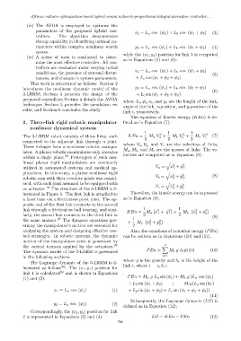
an actuator. 18 The structure of the 3-LRRM is il- 3 3
lustrated in Figure 1. The first link is attached to Therefore, the kinetic energy can be expressed
a fixed base via a frictionless pivot joint. The op- as in Equation (9).
posite end of the first link connects to the second
1
link through a frictionless ball bearing, and simi- KEn = M a ˙x + ˙y 2 + 1 ˙ x + ˙y 2
2
2
larly, the second link connects to the third link in 2 1 1 2 M b 2 2 (9)
the same manner. 37 The dynamic equations gov- + 1 ˙ x + ˙y 2
2
erning the manipulator’s motion are essential for 2 M c 3 3
analyzing the system and designing effective con- Also, the equations of potential energy (PEn)
trol strategies. In robotic systems, the dynamic can be written as in Equations (10) and (11).
motion of the manipulator arms is generated by
3
the control torques applied by the actuators. 38 X
The dynamic model of the 3-LRRM is presented PEn = M i g h i ψ(10) (10)
in the following sections. i=1
where g is the gravity and h i is the height of the
The Lagrange dynamic of the 3-LRRM is il-
39
lustrated as follows : The (x 1 , y 1 ) position for link i, where i = a, b, c.
link 1 is calculated 39 and is shown in Equations
(1) and (2): PEn = M a g L a sin (ψ 1 ) + M b g (L a sin (ψ 1 )
+ L b sin (ψ 1 + ψ 2 ) + M c g(L a sin (ψ 1 )
x 1 = L a cos (ψ ) (1) + L b sin (ψ 1 + ψ 2 ) + L c sin (ψ 1 + ψ 2 + ψ 3 ))
1
(11)
Subsequently, the Lagrange dynamic (LD) is
y 1 = L a sin (ψ 1 ) (2)
defined as in Equation (12);
Correspondingly, the (x 2 , y 2 ) position for link
2 is represented in Equations (3) and (4): LD = KEn − PEn (12)
709