
Page 170 - IJOCTA-15-4
P. 170
Oleiwi et al. / IJOCTA, Vol.15, No.4, pp.706-727 (2025)
as 1/N, is not adjusted dynamically. Instead, it
1 N must be tuned offline alongside the NN parame-
G(s) = K p + K i + K d s (39)
PID ters prior to deployment.
S S + N
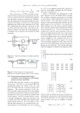
The performance of a PID controller is deter- Figure 4 illustrates the architecture of the
mined by three primary gain parameters: K p , K i , NN component within the STNN–PID controller.
and K d , which control the proportional, integral, The network comprises several layers, including
and derivative responses, respectively. Addition- an input layer, a first hidden layer, and an acti-
ally, the parameter N represents the filter’s corner vation function. The input layer consists of four
frequency and plays a critical role in attenuating neurons, each representing a key variable: the ap-
high-frequency noise in the derivative term. Fig- plied torque for the i-th link T i , the desired an-
ure 2 illustrates the schematic structure of the gular position (ψ ), the actual angular position
ri
con-PID controller with a filter. For further clar- (ψ ai ), and the position error between the desired
ification, Figure 3 presents the block diagram of and actual angles (e ). The first hidden layer also
ψi
a feedback control system that includes the PID contains four neurons, each connected to all neu-
controller. rons in the input layer as well as to a bias neuron
through weighted connections. For each neuron
in the first hidden layer, the activation function
H(Σ) is applied to the weighted sum of its in-
puts to produce the neuron’s output. The input
vector is defined in Equation (40), while the out-
puts of the first hidden layer neurons are given in
Equations (41) and (42). The specific activation
function employed is described in Equation (43):
ψ ai
ψ
ri
e ψi Input layer neurons of the neural network
Figure 2. Proportional-integral-derivative controller T i
with filter 1
(40)
P 1
(k)
1 w11 w12 w13 w14 w15
P 1
2
(k) w21 w22 w23 w24 w25
=
P
(k) 1 w31 w32 w33 w34 w35
3
P 1 w41 w42 w43 w44 w45
(k)
4
Figure 3. Block diagram of a conventional
ψ ai
proportional-integral-derivative (PID) control system
ψ
ri
3.2. Proportional-integral-derivative e ψi
controller with integrated self-tuning T i
neural network and filter 1
(41)
A STNN–PID controller consists of two primary
components. The first is a pre-trained NN that 1 H( P (k) )
1
1
1
dynamically adjusts the values of K p , K i , and S (k) H( P (k) )
1
1
K d in the PID controller to improve system per- S (k) P 2
2
1 = (k) 1 (42)
H
formance. The second component is the con- S (k) 3
3
1
PID controller, which generates the control signal S (k) H P (k) 1
4
by applying proportional, integral, and derivative 4
P 1
operations to the error between the desired and where (k) is defined as the sum of input con-
i
actual outputs. The NN is trained offline to meet nections for each neuron in the first hidden layer,
1
a specific performance objective and then used while S (k) represents the i-th output of the same
i
to supply the PID controller with updated gain layer’s neuron, and wij are weights of connec-
values during operation. It is important to note tions.
that the filter parameter N, representing the cor- 2
ner frequency (or equivalently, the time constant H(Σ) = 2 − Σ 2 × e −Σ (43)
712