
Page 175 - IJOCTA-15-4
P. 175
African vultures optimization-based hybrid neural network–proportional-integral-derivative controller...
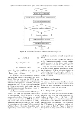
Figure 8. Flowchart of the African vultures optimization algorithm
end-effector trajectories for each proposed con-
ψ r1 = sin(0.2πt) (76) troller.
The results indicate that the NN–PID con-
troller demonstrates smooth trajectory tracking,
ψ r2 = sin(0.2πt − π/4 ) (77) rapid convergence to the desired path, and the
lowest ITSE compared to the other controllers.
Among the proposed controllers, the NN–PID
ψ r3 = sin(0.2πt − π/2) (78)
controller exhibits superior performance, achiev-
where the initial conditions are: ψ r1 = 0, ing the minimum ITSE, as well as the shortest rise
ψ r2 = −0.7, and ψ r3 = −1 rad, and x(0) = and settling times. In contrast, the con-PID con-
1.0769 m, y(0) = −0.4580 m. troller exhibits the weakest performance across all
All necessary information regarding the nom- evaluated metrics.
inal model and simulation setup had been estab-
lished. The next step used the AVOA in con- 6. Robust performance
junction with the nominal model to optimize the
To assess the effectiveness and resilience of each
parameters of all proposed controllers, aiming to
proposed controller, this section evaluates their
minimize the ITSE. Due to the stochastic nature
robustness under varying test conditions without
of AVOA, each controller configuration was sim-
modifying the controllers’ parameters.
ulated 10 times to obtain the optimal results for
each proposed controller.
6.1. Change initial position
Table 2 summarizes the number of tunable pa-
rameters and their corresponding search spaces To evaluate the controllers’ robustness to changes
for each controller. The ITSE values for all rec- in initial conditions, the joint angles were ini-
ommended controllers, obtained under two initial tialized as follows: Psi-1 = 0.2, Psi-2 = −0.5,
conditions, are presented in Table 3. Addition- and Psi-3 = −0.8 rad. This test examined the
ally, for the initial condition (0.15, −0.55, −0.85), performance of the proposed controllers under
performance metrics including rise time, settling different initial configurations. The correspond-
time, maximum overshoot, and ITSE are provided ing ITSE values for the trajectory tracking task
in Table 4. Figure 9 illustrates the position track- are presented in Table 5. Figure 10 illustrates
ing accuracy, control signal outputs, and the x–y the position tracking results for Psi-1, Psi-2, and
717