
Page 156 - JCAU-6-2
P. 156
Journal of Chinese
Architecture and Urbanism RuiXue Multi-Hall in reciprocal structures
At the software control level, FURobot serves as a
bridge between designers and robots. It not only translates
models into processing paths and codes but also simulates
potential issues during robotic processing using digital
twin technology and makes corresponding adjustments.
For each component, the robot requires a series of different
operations and their corresponding processing paths
(Figure 21).
The first step involves determining the precise location
of the component to be processed within the factory
environment, achieved through visual positioning
technology. Subsequently, geometric calculations are
performed on the slots to be milled to determine the most
suitable tools and processes. Deep slots in typical steel-
wood joints intended for steel plate insertion are processed
by another robot. During this process, the first robot can
replace the special milling cutter required for subsequent
hole punching and slot opening (Figure 22). It is important
to note that the cylindrical body of the milling cutter affects
the design form of the nodes during processing, primarily
causing rounding at the node turning position.
The robotic mass customization method effectively
Figure 19. Structural unit classification. Source: Drawing by Yingzi Hu ensures the smooth completion of large-scale customized
and editing by Yueyang Wang
components, enhancing processing accuracy while
were constructed using 450×180 mm glued laminated significantly reducing processing time and costs.
timber beams. For B3 beams, which were subjected to The installation of a timber structure is predicated on
the largest axial forces, we opted for more stable wood- a three-beam unit, as illustrated in Figure 23. Initially, the
clad steel beams to meet their tensile and compressive central axis of the positioning line is located on the plane
requirements. B4 beams, known for their superior and then raised to the desired elevation. Throughout the
structural stability and ease of on-site construction construction process, the central axis at the intersection
positioning, were constructed using 355×16 mm circular of each beam is periodically reassessed for precision,
steel beams (Figure 20). employing total stations, GPS-RTK technology, or drone
scanning. This practice aims to ensure accuracy and
5.2. Locally-rooted digital construction minimize the accumulation of discrepancies.
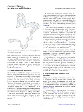
The assembly of prefabricated complex shell structures 6. 3D-printed panels based on shell
imposes stringent requirements on processing accuracy geometry
and efficiency. Given the project’s need for glued laminated
timber components with varying shapes, sizes, hole A large-scale modified plastic 3D-printed roof was chosen
positions, and slot openings, maintaining processing to complete the intricate, double-curved geometric shell
accuracy within ±1 mm for joint fabrication is crucial. surface of the project. The individual roof panels were
Therefore, the utilization of robotics is instrumental in processed to create a layered undulation running parallel
ensuring the precision of interconnected components. to the curved surface’s edge. This undulation mirrors the
The project employs two KUKA 7-axis robots. One is building’s dynamic, aerodynamic form of the building
equipped with a main spindle motor boasting a maximum (Figures 24 and 25).
rotation speed of 18,000 rpm, while the other is fitted with The integration of a reciprocal timber structure and a
an electric chainsaw designed for cutting and slotting. 3D-printed roof (Figure 26) in the design-construction
A deepening process toolkit, specifically developed for process exemplifies the boundless potential of digital
digital timber construction, allows designers to select architecture during the design refinement phase and
appropriate processes and tools based on the specific type its capacity to enhance intelligent execution during the
of joints. construction stage.
Volume 6 Issue 2 (2024) 14 https://doi.org/10.36922/jcau.1635