
Page 151 - JCAU-6-2
P. 151
Journal of Chinese
Architecture and Urbanism RuiXue Multi-Hall in reciprocal structures
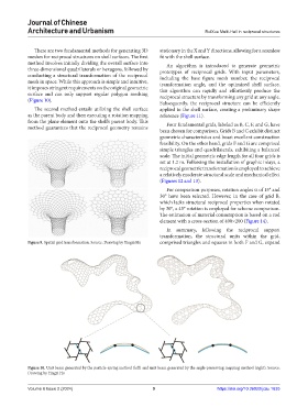
There are two fundamental methods for generating 3D stationary in the X and Y directions, allowing for a seamless
meshes for reciprocal structures on shell surfaces. The first fit with the shell surface.
method involves initially dividing the overall surface into An algorithm is introduced to generate geometric
three-dimensional quadrilaterals or hexagons, followed by prototypes of reciprocal grids. With input parameters,
conducting a structural transformation of the reciprocal including the base figure mesh number, the reciprocal
mesh in space. While this approach is simple and intuitive, transformation angle, and the optimized shell surface,
it imposes stringent requirements on the original geometric this algorithm can rapidly and effortlessly produce the
surface and can only support regular polygon meshing reciprocal structure by transforming any grid at any angle.
(Figure 10).
Subsequently, the reciprocal structure can be efficiently
The second method entails utilizing the shell surface applied to the shell surface, creating a preliminary shape
as the parent body and then executing a rotation mapping reference (Figure 11).
from the plane element onto the shell’s parent body. This Four fundamental grids, labeled as B, C, F, and G, have
method guarantees that the reciprocal geometry remains
been chosen for comparison. Grids B and C exhibit distinct
geometric characteristics and boast excellent construction
feasibility. On the other hand, grids F and G are comprised
simple triangles and quadrilaterals, exhibiting a balanced
scale. The initial geometric edge length for all four grids is
set at 1.2 m. Following the installation of graphic inlays, a
reciprocal geometric transformation is employed to achieve
a relatively moderate structural scale and mechanical effect
(Figures 12 and 13).
For comparison purposes, rotation angles α of 15° and
30° have been selected. However, in the case of grid B,
which lacks structural reciprocal properties when rotated
by 30°, a 45° rotation is employed for scheme comparison.
The estimation of material consumption is based on a rod
element with a cross-section of 400×200 (Figure 14).
In summary, following the reciprocal support
transformation, the structural units within the grid,
Figure 9. Spatial grid transformation. Source: Drawing by Yingzi Hu comprised triangles and squares in both F and G, expand
Figure 10. Unit beam generated by the particle-spring method (left) and unit beam generated by the angle-preserving mapping method (right). Source:
Drawing by Yingzi Hu
Volume 6 Issue 2 (2024) 9 https://doi.org/10.36922/jcau.1635