
Page 154 - JCAU-6-2
P. 154
Journal of Chinese
Architecture and Urbanism RuiXue Multi-Hall in reciprocal structures
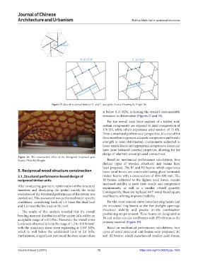
Figure 15. Special reciprocal states of B- and C-type grids. Source: Drawing by Yingzi Hu
is below 0.15 MPa, indicating the system’s commendable
resistance to deformation (Figures 17 and 18).
For the overall axial force analysis of a timber roof,
certain components are exposed to axial compression of
170 kN, while others experience axial tension of 75 kN.
From a structural performance perspective, it is crucial for
these members to possess adequate compressive and tensile
strength to resist deformation. Components subjected to
lower tensile forces and appropriate compressive forces can
have more balanced material properties, allowing for the
design of relatively uncomplicated connections.
Figure 16. The construction effect of the hexagonal reciprocal grid.
Source: Photo by Wongke Based on mechanical performance calculations, four
distinct types of wooden structural unit beams have
been proposed. The B1 and B2 beams, which experience
5. Reciprocal wood structure construction lesser axial forces, are constructed using glued laminated
5.1. Structural performance-based design of timber beams with a cross-section of 450×180 mm. The
reciprocal timber units B3 beams, subjected to the highest axial forces, require
increased stability to meet their tensile and compressive
After conducting geometric optimization of the structural requirements, as well as a smaller overall quantity.
members and developing the spatial model, the initial Consequently, these are replaced with wood-faced square
evaluation of the structural performance of the system was steel beams, offering improved stability.
carried out. This assessment was performed under specific
conditions, considering loads of 1.3 times the dead load For the outer rational curve boundary ring beams and
and 1.5 times the live load on the roof. the structural ring beams at the five skylight openings,
structural stability and precise on-site construction
The results of this analysis revealed that the overall
bending moment distribution of the system falls within an positioning are paramount. These beams are designated as
B4 and utilize circular steel beams with 355×16 mm as the
acceptable range of ±20 kNm. Moreover, the overall stress primary material (Figure 19).
levels were observed to be in the range of 1.2 to -0.9 N/mm ,
2
with the maximum shear stress registering at 1.197 MPa, Based on mechanical performance calculations, four
which is well below the established limit of 2.0 MPa. types of wood structural unit beams were proposed. B1
Furthermore, a significant portion of the shear stress values and B2 beams, which experienced smaller axial forces,
Volume 6 Issue 2 (2024) 12 https://doi.org/10.36922/jcau.1635