
Page 148 - JCAU-6-2
P. 148
Journal of Chinese
Architecture and Urbanism RuiXue Multi-Hall in reciprocal structures
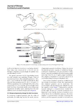
Figure 4. Rationalization of boundary curves. Source: Drawing by Yingzi Hu
Figure 5. Five major parameters for shell design and battery arrangement. Source: Drawing by Philip F. Yuan
coefficient of elasticity, denoted as L, was further adjusted. of appropriate geometric tessellations. Taking into account
Three values were considered for L: 0.8, 0.9, and 1.0. the potential geometric requisites of architectural design,
Through a comparison of spatial height, the optimal value construction considerations, and cost constraints, we have
was determined to be 0.9. chosen 11 geometric tessellations, all of which possess a single
The optimal parameters for the shape-finding process vertex type, from the set of regular polygon tessellations.
of a shell structure were established through a series of This category of tessellation is commonly referred to as
numerical experiments. Three adjustable parameters – W, L, Archimedean tiling (Grünbaum & Shephard, 1987).
and S – were considered. The results revealed that the ideal Once we have identified a geometric tessellation grid
values for these parameters were W = 80, L = 0.9, and S = 3. that satisfies the necessary criteria, the transformation
With these parameters, the overall height of the shell surface into reciprocal geometry can be undertaken. The
ranged from 3.2 to 7.4 m, and the indoor net height varied process begins with determining the midpoint for each
from 2.6 to 6.8 m. These results fulfill a variety of functional line segment within Figure 7. Subsequently, each line
requirements for indoor space, spanning from the main segment undergoes a counterclockwise rotation by a
exhibition area to the transitional gray space (Figure 6). specific angle, denoted as α, around its midpoint. It is
important to note that the direction of rotation is not a
4.3. Reciprocal geometry design for shell structures critical factor, but for illustrative purposes, this article
To incorporate reciprocal geometry into the realm of employs a counterclockwise direction. Following this
architecture, the initial step involves the careful selection rotation, each line segment is extended in both directions
Volume 6 Issue 2 (2024) 6 https://doi.org/10.36922/jcau.1635